Professional Installation Guide for Cold Chain Solution — Thermo King Trailers Units Models with Smart Reefer
User Guide
0 mins to read
This document is the installation guide for Thermo King trailer unit models with Smart Reefer 2, 3, and 4 controllers. This document provides technical information, installation instructions, and the procedure to install the GO device, GEO-CCIPBOX or IOX-COLD RUGGED, and communication protocol harness.
For Cold Chain Solution (Thermo King Trailer Units Models with Smart Reefer 2, 3, and 4 Controllers)


Introduction
This document is the installation guide for Thermo King trailer unit models with Smart Reefer 2, 3, and 4 controllers. This document provides technical information, installation instructions, and the procedure to install the GO device, GEO-CCIPBOX or IOX-COLD RUGGED, and communication protocol harness.
Preparing for Installation
Before installing this solution, confirm that you have the following tools and components:
Tools
|
Components
Product | Reference | Quantity | Quantity | |
IOX Device ✱ NOTE: Must be the GEO-CCIPBOX or the IOX-COLD RUGGED | GEO-CCIPBOX (Discontinued) | IOX-COLD RUGGED | 1 | |
Thermo King Smart Reefer 2, 3, and 4 RS-232 communication protocol harness | HRN-CL03S51 (Discontinued) (GEO-CCIPBOX) | (IOX-COLD RUGGED) | 1 | |
GO Device | GO9 (GEO-CCIPBOX) | GO9 RUGGED (IOX-COLD RUGGED) | 1 | |
Three wire harness for G09 RUGGED only used if GO9 RUGGED is installed | (IOX-COLD RUGGED) | 1 | ||
Installation Instructions
This document covers the following installation processes:
IOX-COLD RUGGED Installation Instructions
- Installing this solution (IOX-COLD RUGGED)
GEO-CCIPBOX Installation Instructions
- Installing this solution (GEO-CCIPBOX)
IMPORTANT NOTICE: The section below covers the discontinued / end-of-life (EoL) GEO-CCIPBOX and its cold chain harness.
- For new installations: Do not use this device for new deployments. Instead, use IOX-COLD RUGGED & GO9 RUGGED combination with the proper cold chain harness (refer to the components table above).
- For field maintenance of existing installations: These instructions remain valid for maintenance and troubleshooting purposes only.
Before installation, you must open the right and/or center compartments of the refrigeration unit, depending on the location of the controller and its master switch.
WARNING! Turn off the vehicle's engine and the microprocessor's main switch before installation. Failure to do so may result in unintended motor activation, sudden vehicle shutdown, erratic vehicle behavior, component/accessory damage, or pose an electrical hazard leading to death or serious injury.
! IMPORTANT: Professional installation (Certified Geotab® Installer or equivalent) is required for the safe and proper installation of this product (harness and/or IOX). The installer must have sufficient technical knowledge and expertise for the respective installation.
WARNING! All IOX-COLD RUGGED, GEO-CCIPBOX, and GO RUGGED cabling cabling must be securely fastened and routed clear of hot surfaces, vehicle controls, and moving components in the engine or refrigeration unit. Failure to do so may result in damaged components, refrigeration unit malfunction, or collisions leading to death or serious personal injury.
IMPORTANT! All powered connections must be fitted with overcurrent limit protection. Geotab offers the HRN-5AFUSKIT, this can help minimize configuration complexity, reduce installation time, and improve reliability.
Installing this solution (IOX-COLD RUGGED)
1 | Connect HRN-RCCTKSR2 to the IOX-COLD RUGGED |
| ||||||||||
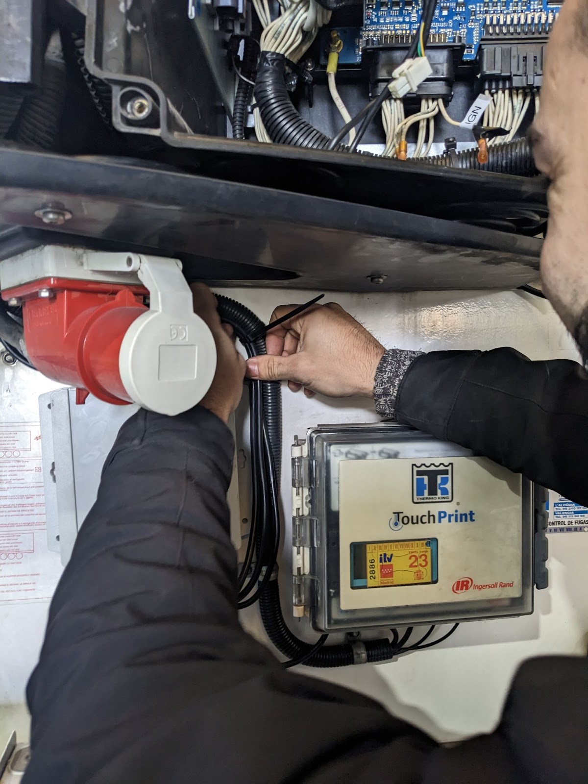
2 | Depending on the IOX-COLD RUGGED location, route the HRN-RCCTKSR2 harness toward the controller compartment. If needed, use a cable guide to route through the original unit harness. ! IMPORTANT: Different unit models may have different wiring pass-through access points behind the controller’s compartment. Use appropriate access points to connect the IOX-COLD RUGGED to the compartment. | |||||||||||
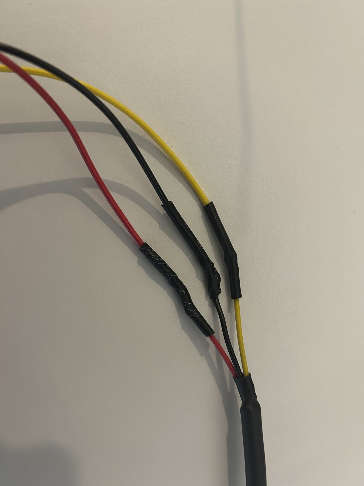
3 | Connect the HRN-RCCTKSR2 three wire harness to the GO RUGGED three-wire harness HRN-RW03K4. Make sure to protect each connection to avoid electrical short circuits on the installation.
! IMPORTANT: Make sure to complete step 4 after proceeding to this step. If step 4 is performed with the HRN-RCCTKSR2 already connected to the board, its red loose wire will have refrigeration constant power and might cause a short circuit if not handled properly. |
| ||||||||||
4 | Connect the HRN-RCCTKSR2 harness to :
If all these connectors are already populated on the controller :
| SR-2 controller board SR-3 controller board SR-4 controller board | ||||||||||
5 | Once the HRN-RCCTKSR2 routing and connections are completed, follow the steps (start from step 4) outlined in the quick start guide, which can be found here: gtb.link/ioxcoldrugged Do not forget to fasten all the installed cables to the refrigeration unit harnesses and stationary mechanical parts of the asset to secure the cable management. ! IMPORTANT: The GO9 RUGGED must be powered by the three loose wires located on harness HRN-RCCTKSR2. For more details, refer to the quick start guide. ! IMPORTANT: The use of the complete MyInstall tool (via MyAdmin platform login Access) is mandatory for every installation to correctly configure the IOX-COLD RUGGED. If you do not do this, data will not be obtained correctly. |
|


Installing this solution (GEO-CCIPBOX)
1 | Depending on the IP Box location, route the HRN-CL03S51 harness and the IP Box three-wire harness toward the controller compartment. If needed, use a cable guide to route through the original unit harness. ! IMPORTANT: Different unit models may have different wiring pass-through access points behind the controller’s compartment. Use appropriate access points to connect the IP Box to the compartment. |
|
2 | Connect the HRN-CL03S51 harness to the J9 or J10 controller connector. Connect the IP Box three-wire harness to the controller board. For detailed instructions for the IP Box three-wire harness connection, refer to ✱ NOTE: For Ground and Constant Power (VCC) connection, use the ring terminals available in the GEO-CCIPBOX kit to crimp onto each wire. | SR-2 controller board
SR-3 controller board
SR-4 controller board
|
3 | Group the loose accessory gland cable wires and route it in or near the controller compartment, as the cable will not be used. | |
4 | Fasten the IP Box cables to the unit harnesses and stationary mechanical parts of the asset to secure the cable management. |
|
5 | Once complete, close the refrigeration unit compartment and turn on the microprocessor switch and the HMI. The GO device powers on, and initiates the provisioning and firmware updates. |
|
6 | Verify that the GEO-CCIPBOX has been installed correctly. MyInstall: Validate the installation using the MyInstall tool. You need a secure MyAdmin login to use this tool. If you do not have one, refer to the Creating MyInstall Credentials section of the MyInstall user guide. ! IMPORTANT: The use of this tool is mandatory for every installation. If the GEO-CCIPBOX is not configured correctly, it will not transmit correct data. |
|


Important Safety Information and Limitations of Use
For the latest version of the Limitations of Use, please visit: https://gtb.link/k6Fp0w
WARNING! Do not attempt to install, configure or remove any product from any vehicle while the vehicle is in motion or powered up. All installation, configuration or removal must be done only in stationary vehicles which are securely parked. Attempting to service units while being operated could result in malfunctions or accidents, leading to death or serious personal injury.
WARNING! All in-vehicle devices and related cabling must be securely fastened and kept clear of all vehicle controls, including gas, brake and clutch pedals. You must inspect devices and cabling on a regular basis to ensure all devices and cabling continue to be securely attached. Loose cabling or devices may impede the use of vehicle controls, resulting in unanticipated acceleration, braking or other loss of vehicle control, which could lead to death or serious personal injury. Improperly fastened in-vehicle devices may detach and impact operators upon sudden acceleration or deceleration, which may cause injury.
WARNING! If at any point after an in-vehicle device is installed a warning light illuminates on the vehicle dash or the vehicle stalls or has a marked drop in performance, shut off the engine, remove the device, and contact your Reseller. Continuing to operate a vehicle with these symptoms can cause loss of vehicle control, and serious injury.
WARNING! Your in-vehicle devices must be kept clear of debris, water and other environmental contaminants. Failure to do so may result in units malfunctioning or short-circuiting that can lead to a fire hazard or vehicle damage or serious injury.
WARNING! Do not attempt to remove the devices from the vehicle in which they are originally installed for installation in another vehicle. Not all vehicles share compatibility, and doing so may result in unexpected interactions with your vehicle, including sudden loss of power or shutdown of the vehicle’s engine while in operation or cause your vehicle to operate poorly or erratically and cause death or serious injury and/or vehicle damage.
NOTICE: This product does not contain any user-serviceable parts. Configuration, servicing, and repairs must only be made by an authorized Reseller or Installer. Unauthorized servicing of these products will void your product warranty.
