IOX-COLD Support Document
Support Document
0 mins to read
The IOX-COLD is a multipurpose IOX™ that supports Tachograph, Cold Chain transportation data logging and general expandability for the GO device.
For the most up-to-date version of this document, click here.
The IOX-COLD is a multipurpose IOX™ that supports Tachograph, Cold Chain transportation data logging and general expandability for the GO device.
Key features
Cold chain (refrigeration unit, accessories and thermograph)
- Real-time temperature monitoring, proof of delivery, custom alerts and reporting.
- Error code detection and custom alerts to fleet managers.
- Remote temperature adjustment.
- Remote refrigeration unit start/stop.
- Remote fault clearing.
- Can connect to external door and temperature sensors.
For more information, refer to the Cold Chain Installation sections (Refrigeration unit and Accessories, Thermograph) of the IOX-COLD Installation Guide.
Tachograph
- Automated remote download of vehicle and driver information.
- Automatic driver identification that matches individual drivers with specific vehicles, improving report accuracy on the MyGeotab™ platform.
- Automated downloads occur at regularly scheduled intervals, but can also be done as needed on demand (in accordance with the technical and legal requirements set by the European Union).
- Sends real-time Tachograph data, including driver name, driver status, and other useful information (in accordance with the technical and legal requirements set by the European Union).
Refer to the Installation with a Tachograph section of the IOX-COLD Installation Guide for more information.
Other expandability functionalities
The IOX-COLD allows for custom connectivity to several interfaces:
- CAN bus, RS-232, RS-485, 1-wire, TTL UART
- 4x general-purpose inputs (digital and analog)
- 2x general-purpose outputs
- USB 2.0 charging port
- Power outputs for external peripherals (supply current limit defined by the GO device)
For more information, refer to the Expansion Solutions Installation Guide.
Cold chain supported features
Refrigeration units
The following tables list all refrigeration unit features and controllers that are currently supported by IOX-COLD devices:
Manufacturer controller and/or model | Thermo King Truck Smart Reefer | Carrier Standard | Carrier APX | HWASUNG | Thermo King DSR | Thermo King CSR (coming soon) | GAH/LAE AH1-5B14L-AG controller | GAH/LAE DU5S controller | Carrier Xarios/Pulsor | Carrier Neos/Zephyr/ Viento | Zanotti Uno Series (coming soon) |
Return temp | ✔ | ✔ | ✔ | ✔ | ✔ | ✔ | ✔ | ✔ | ✔ | ✔ | ✔ |
# of supported zones | 3 | 3 | 3 | 2 | 2 | 2 | 1 | 2 | 1 | 1 | 2 |
Ambient temp | ✔ | ✔ | ✔ | ✘ | ✘ | ✘ | ✘ | ✘ | ✘ | ✘ | ✔ |
Discharge temp | ✔ | ✔ | ✔ | ✘ | ✘ | ✘ | ✘ | ✘ | ✘ | ✘ | ✔ |
Evaporator temp | ✔ | ✘ | ✔ | ✘ | ✘ | ✘ | ✔ | ✔ | ✘ | ✘ | ✘ |
Setpoint temp | ✔ | ✔ | ✔ | ✔ | ✔ | ✔ | ✔ | ✔ | ✔ | ✔ | ✔ |
Door probe1 | ✔ | ✔ | ✔ | ✘ | ✔ | ✘ | ✔ | ✔ | ✔ | ✘ | ✔ |
Diesel/electric mode | ✔ | ✔ | ✔ | ✘ | ✘ | ✘ | ✘ | ✘ | ✘ | ✘ | ✔ |
Power switch | ✔ | ✔ | ✔ | ✔ | ✔ | ✔ | ✔ | ✔ | ✔ | ✔ | ✔ |
Engine RPM | ✔ | ✘ | ✔ | ✘ | ✘ | ✘ | ✘ | ✘ | ✘ | ✘ | ✔ |
Total hours³ | ✔ | ✘ | ✔ | ✘ | ✔ | ✘ | ✘ | ✘ | ✘ | ✘ | ✔ |
Engine hours³ | ✔ | ✘ | ✘ | ✘ | ✔ | ✘ | ✘ | ✘ | ✘ | ✘ | ✔ |
Electric hours³ | ✔ | ✘ | ✘ | ✘ | ✔ | ✘ | ✘ | ✘ | ✘ | ✘ | ✔ |
On hours³ | ✔ | ✘ | ✘ | ✘ | ✘ | ✘ | ✘ | ✘ | ✘ | ✘ | ✘ |
Auto/manual mode | ✔ | ✔ | ✘ | ✘ | ✘ | ✘ | ✘ | ✘ | ✘ | ✘ | ✔ |
Engine temp | ✔ | ✔ | ✔ | ✘ | ✘ | ✘ | ✘ | ✘ | ✘ | ✘ | ✘ |
Serial number | ✔ | ✔ | ✔ | ✘ | ✘ | ✘ | ✘ | ✘ | ✘ | ✘ | ✘ |
License plate | ✔ | ✔ | ✔ | ✘ | ✘ | ✘ | ✘ | ✘ | ✘ | ✘ | ✘ |
Fuel level1 | ✔ | ✘ | ✔ | ✘ | ✘ | ✘ | ✘ | ✘ | ✘ | ✘ | ✘ |
Machine type | ✔ | ✘ | ✔ | ✘ | ✔ | ✘ | ✘ | ✘ | ✘ | ✘ | ✘ |
Battery voltage² | ✔ | ✔ | ✔ | ✘ | ✔ | ✘ | ✘ | ✘ | ✘ | ✘ | ✔ |
Alarms | ✔ | ✔ | ✔ | ✘ | ✔ | ✔ | ✔ | ✔ | ✘ | ✘ | ✔ |
Remote command: operation mode | ✔ | ✘ | ✘ | ✘ | ✘ | ✘ | ✘ | ✘ | ✘ | ✘ | ✘ |
Remote command: setpoint adjustment | ✔ | ✘ | ✔ | ✘ | ✔ | ✘ | ✔ | ✔ | ✘ | ✘ | ✔ |
Remote command: alarm clearing | ✔ | ✘ | ✔ | ✘ | ✘ | ✘ | ✘ | ✘ | ✘ | ✘ | ✘ |
Remote command: start/stop | ✔ | ✘ | ✘ | ✘ | ✘ | ✘ | ✘ | ✘ | ✘ | ✘ | ✔ |
1 Only available if a sensor is connected to the refrigeration unit.
2 If available, battery voltage is obtained directly from the refrigeration unit. If not, the GO device voltage is used (visible in MyGeotab).
3 Only a single time value can be stored at a time (total hours, engine hours, electrical hours, on hours).
Thermographs
The following table lists all thermograph features and controllers that are currently supported by IOX-COLD devices:
Manufacturer | Models | Temperature zones | Number of telemetries | Serial number | License plate |
Thermo King | TKDL-PRO, TKDL-SPR, TKDL-DCS | 4 | 4 | ✔ | ✔ |
Thermo King | TouchLog/TouchPrint | 6 | 4 | ✔ | ✔ |
Carrier Transicold | Datacold 500 | 4 | 4 | ✔ | ✔ |
Transcan | 2 ADR, Sentinel, Advance | 4 | 4 | ✔ | ✔ |
Euroscan | Euroscan X1, X2 | 4 | 4 | ✔ | ✔ |
Grupo Buscalia | Thermotrans | 4 | ✘ | ✔ | ✔ |
Carrier Transicold | Datacold 600 | 6 | ✘ | ✔ | ✔ |
Orbcomm | Euroscan X3 | 6 | ✘ | ✔ | ✔ |
Made Sistemi | REC96 | 3 | 2 | ✘ | ✘ |
Apache | Cold Tracer | 6 | 4 | ✔ | ✘ |
Technical specifications and features
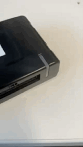
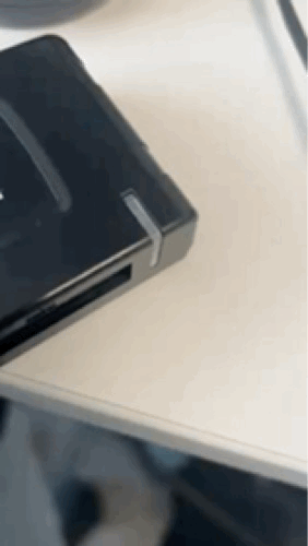
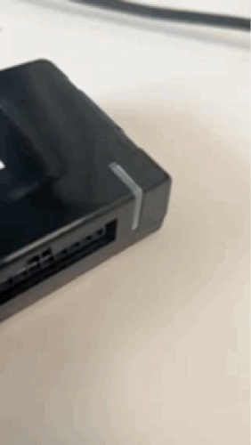
Mechanical | Weight: approx. 145 g Dimensions: 103mm x 53mm x 20mm (LxWxH) Housing: Polycarbonate (PC) |
Voltage | 12V / 24V |
Power consumption of IOX-COLD on GO9 daisy-chain | Typical Consumption : 400mW NOTICE:
|
GO9 can source a maximum total current to the IOX in daisy-chain | 2750 mA at 12V / 24V ✱ NOTE: For each additional IOX in the daisy-chain, add the max current draw, and do not exceed the maximum total IOX current draw. |
Temperature rating | -40ºC to 85ºC |
Interfaces | CAN Bus
RS-232 (Communication with thermographs)
RS-232 or RS-485, configurable (Communication with refrigeration units)
TTL UART (Communication with refrigeration units) Used via General Purposes Inputs and Outputs, two configurations possible:
I2C (Communication with refrigeration units) Used via General Purposes Inputs and Outputs, two available channels:
KLINE/D8 (Communication with tachographs - real time data functionality) 1-WIRE (Communication with external sensor (i.e. temperature probes))
|
Connectors |
Male Mini-USB Type-B connector: Daisy chain power and CAN in Female Mini-USB Type-B connector: Daisy chain power and CAN out Jack A or JA (43045-0409): 4-pin connector, connection to thermographs (EU market only) Jack B or JB (43045-0609): 6-pin connector, Connection to tachographs (EU market only) Jack C or JC (43045-2209): 22-pin connector, Cold Chain and Expandability functionalities connectivity |
Inputs/outputs | Inputs (x4): IN1, IN2, IN3, IN4. Analog and digital inputs. Outputs (x2): OUT1, OUT2. |
Input logic levels | Ground - High: The IOX shall classify the input as logic LOW if it is <100mV, and as logic HIGH when the input voltage is ≥ 3.3V. Ground - Float: The IOX shall classify the input as logic LOW if it is floating, and as logic HIGH when the input voltage is <100mV. Float - High: The IOX shall classify the input as logic LOW when it is floating, and as logic HIGH when the input is ≥ 3.3V. |
Flash memory | Density: 32-Mb Speed: 104 MHz |
Visual status | TriColor LED, traffic light-like, indicates general status |
Installation | Male Mini-USB connector connects to the GO device or another IOX harness. Jack A, Jack B and Jack C used depending on the installation use cases. See installation instructions for details. |
Compatible devices | GO9® and newer |
Compliance | FCC, ISED, NOM, CE, REACH, RoHS, WEEE, CalProp 65, RCM, ANATEL, UKCA, SDPPI |

Harness options
The IOX-COLD requires the additional harnesses for successful vehicle installation, which depend on the specific installation scenario. Refer to the Harness Identification and Application document for more information on the best harness for your application.
Installation scenarios
The following diagram shows the device’s possible installation scenarios:

! IMPORTANT: To ensure correct communication between the GO9 device and the IOX-COLD, the GO device must be on firmware version X.42.32 or later.
IOX-COLD installation instructions
Installation instructions are outlined in the quick start guide document.
The quick start guide document is available here: gtb.link/ioxcold
IOX-COLD troubleshooting
This section guides Partners through the troubleshooting process for issues related to IOX-COLD.
Identify the issue
Before contacting Support, please attempt to identify whether the issue is hardware or application related. The issue is hardware related if there is a problem with the IOX-COLD. The issue is application related if there is a problem with MyGeotab.
Gather the information
Before troubleshooting, please follow the steps below to gather all the necessary information related to the issue:
Hardware-related issues
If the issue is hardware related, follow these steps:
1 | Record the information of any hardware that is currently in use:
|
2 | Check for connectivity and installation issues:
✱ NOTE: Regardless of hardware issues, always make sure to check each and every connection, including harnesses and/or the IOX, as applicable. The vast majority of issues result from loose or insecure connections. |
3 | For more detailed troubleshooting steps, see the section on Troubleshooting the Issue. |
Application-related issues
If the issue is MyGeotab-related, please contact Support. Before doing so, record the following information:
- Database name,
- GO device serial number (12 characters, visible on the device, starts with G),
- IOX-COLD serial number,
- Tachograph model and version, and
- Make, model, year and VIN of the vehicle in which the hardware is installed.
Troubleshoot the issue
Once basic information is collected, please refer to the IOX-COLD Troubleshooting Matrix for more detailed troubleshooting steps. Some issues may require advanced troubleshooting. If your issue is not listed or solved with the proposed solutions, please contact Support. The IOX-COLD device has a status LED that produces a series of blinks followed by a pause. The first blink corresponds to the first row of the matrix, the second blink corresponds to the second row, and so on. Ensure the ignition is ON when checking the installation status. If the LED is OFF, it could be due to a power problem or a device failure. Check if the GO device LEDs are on. If so, check that the IOX harness is correctly plugged to the GO Device. It could be a power issue with the GO device.
✱ NOTE: If the problem is not resolved, repeat the installation with another IOX-COLD. If the problem persists, please contact Support.
IOX-COLD troubleshooting matrix
LED sequence | LED state | Device status | Sample video | Recommended action | Additional notes |
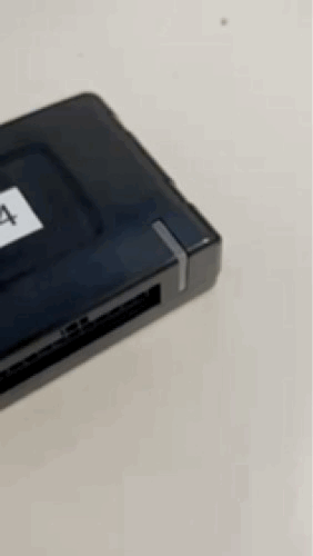
Slow white flashes, continuous | Initialization / booting up ongoing |
| Do not unplug or touch the device Wait for device to stop initializing (LED state will change) | ||
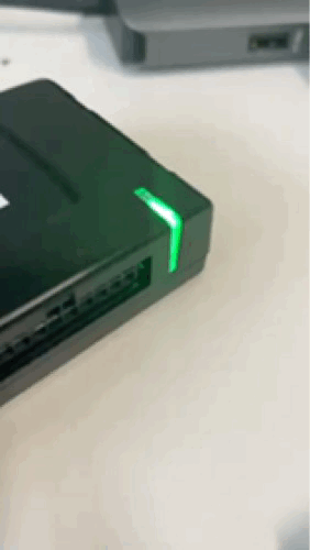
Solid green | Switched ON and working as expected |
| None | Ignition and power ON - no issues or warnings from all installed and configured modules. | |
Fast green flash occurring every 3 seconds, continuous | Low Power Mode |
| None | Triggered when the GO Device goes into Low Power mode. | |
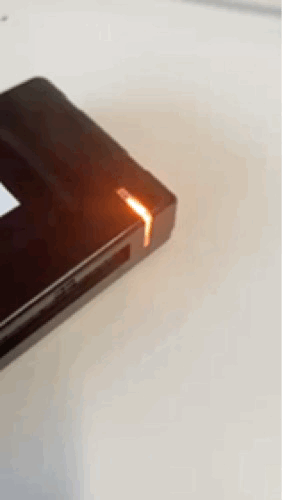
One orange flash, continuous | CAN IOX communication issue |
| No connection to GO device. To troubleshoot, if this persists, check if the GO device is awake and is connected to the IOX-COLD following the Installation Instructions and Termination Shunt sections. | ! IMPORTANT: When more than one of these issues are identified, the device displays only one sequence at a time, prioritized by importance with 1 being the highest importance and 4 being the lowest. 1) IOX communication issue 2) RCU communication issue 3) Thermograph communication issue 4) Tachograph communication issue | |
Two orange flashes, continuous | RCU (Refrigeration control unit) communication issue |
| No communication with the RCU. To troubleshoot, check connections according to the installation guide. | ||
Three orange flashes, continuous | Thermograph communication issue |
| No communication with the thermograph. To troubleshoot, check connections according to the installation guide. | ||
Four orange flashes, continuous | Tachograph communication issue |
| No communication with the tachograph. To troubleshoot, check connections according to the installation guide. |
! IMPORTANT: If the problem is not resolved, repeat the installation with another IOX-COLD. If the problem persists, please contact Support.
Important Safety Information and Limitations of Use
WARNING! Do not attempt to install, configure or remove any product from any vehicle while the vehicle is in motion or otherwise in operation. All installation, configuration or removal must be done only in stationary vehicles which are securely parked. Attempting to service units while being operated could cause malfunctions or accidents, leading to death or serious personal injury.
WARNING! All in-vehicle devices and related cabling must be securely fastened and kept clear of all vehicle controls, including gas, brake and clutch pedals. You must inspect devices and cabling on a regular basis to ensure all devices and cabling continue to be securely attached. Loose cabling or devices may impede the use of vehicle controls, resulting in unanticipated acceleration, braking or other loss of vehicle control, which could lead to death or serious personal injury. Improperly fastened in-vehicle devices may detach and impact operators upon sudden acceleration or deceleration, which may cause injury.
WARNING! If at any point after an in-vehicle device is installed a warning light illuminates on the vehicle dash or the vehicle stalls or has a marked drop in performance, shut off the engine, remove the device, and contact your Reseller. Continuing to operate a vehicle with these symptoms can cause loss of vehicle control, and serious injury.
WARNING! Your in-vehicle devices must be kept clear of debris, water and other environmental contaminants. Failure to do so may cause units malfunctioning or short-circuiting that can lead to a fire hazard or vehicle damage or serious injury.
WARNING! Do not attempt to remove the devices from the vehicle they were originally installed in for installation in another vehicle. Not all vehicles share compatibility, and doing so may cause unexpected interactions with your vehicle, including sudden loss of power or shutdown of the vehicle’s engine while in operation or cause your vehicle to operate poorly or erratically and cause death or serious injury and/or vehicle damage.
NOTICE: This product does not contain any user-serviceable parts. Configuration, servicing, and repairs must only be made by an authorized Reseller or Installer. Unauthorized servicing of these products will void your product warranty.
Regulatory Statements
USA

