IOX-COLD and IOX-COLD RUGGED — Refrigeration Unit and Accessories Solutions Installation Guide
Support Document
0 mins to read
Refrigeration unit data can then be viewed and analyzed in the Asset Monitoring view in the MyGeotab platform.
Refrigeration Unit and Accessories Solutions Installation Guide
Introduction
Before installation, refer to the Cold Chain Harness Compatibility document to determine which integration products (harnesses) are needed depending on the corresponding cold chain machine. Refrigeration unit data can then be viewed and analyzed in the Cold Chain view in the MyGeotab™ platform. For more information, refer to the Cold Chain view - User guide.
Note that specific installation instructions depend on the refrigeration unit make, model, and controller. Refer to the following table to find the instructions you are required to use.
Finally, if there is a Thermograph in the installation, refer to the Thermograph Solution Installation Guide.
! IMPORTANT: Once the required installations between the IOX-COLD/IOX-COLD RUGGED and its compatible solutions (Refrigeration unit and accessories, Thermograph, Tachograph, Expansions) have been completed, the IOX-COLD/IOX-COLD RUGGED must be installed with GO9/GO9 RUGGED devices as outlined in the quick start guides.
The quick start guides for IOX-COLD and IOX-COLD RUGGED can be found in the following links:
- IOX-COLD: gtb.link/ioxcold
- IOX-COLD RUGGED: gtb.link/ioxcoldrugged
✱ NOTE: Geotab Cold chain solution integrates with several 3rd-party 1-wire temperature sensors (DS18B20) and door sensor switches. The installer, customer, partner or reseller should source their preferred external sensors. To be compatible with IOX-COLD and IOX-COLD RUGGED, sensors must adhere to the following specifications:
- Temperature sensors must be a DS18B20-type with the standard 3-wire configuration. Typically yellow for data, red for VCC, and black for GND, but wire colors may vary depending on the manufacturer.
- While various types of door sensors are supported, magnetic sensors are preferred. The sensor must meet the fundamental requirement of providing a two-state output to distinctly signal if a door is open or closed. A normally closed (NC) configuration preferred. Refer to the diagram below for further details:

IOX-COLD
! IMPORTANT: Note that wire colors on ordered harnesses may vary slightly in tone from the pictures shown in this document. For example, the green, grey, and brown wires may appear in lighter or darker shades. These variations are purely aesthetic and do not change the installation process.
Cold chain solution installation - refrigeration unit
Typical installation connection schematic
The following schematic depicts a typical installation, with the required refrigeration unit harness depending on the make, model, and controller. Refer to the Cold Chain Harness Compatibility document to determine which harness is required for your particular situation.

Installation instructions
Manufacturer | Refrigeration unit model/controller | Installation document |
Hwasung | - | |
Thermo King | T-Series | |
Carrier Transicold | Supra | |
Carrier Transicold | Xarios/Pulsor | |
Carrier Transicold | Neos/Zephyr/Viento | |
LAE/GAH | GAH units with LAE AH1-5B14L-AG controller | |
LAE/GAH | GAH SR350/SR351 units with LAE DU5S controller | |
Thermo King | Direct Smart Reefer controller (DSR) | |
Carrier Transicold | APX Controller |
Cold chain installation - accessories
Typical installation connection schematic
The following schematic depicts a typical installation, with the required refrigeration unit harness depending on the make, model, and controller. Refer to the Cold Chain Harness Compatibility document to determine which harness is required for your particular situation.

Preparing for installation
Ensure that you have all of the following:
Tools
|
|
Components
Product | Reference | Quantity |
IOX-COLD | IOX-COLD | 1 |
Refrigeration unit communication protocol harness | Will depend on the cold chain unit model/controller. Refer to the compatibility list and the harness catalog for more information. | 1 |
1-wire temperature sensors
1-wire temperature sensors allow you to register temperature values in vehicles without connecting to a thermograph.
It is possible to connect up to 3 temperature sensors in parallel.
Installation instructions
1 | After installing temperature sensor(s) on the vehicle, route their wiring to the IOX-COLD cold chain harness’ loose wires. | |
2 | Connect the Red and Black sensor wires to the IOX-COLD cold chain harness’ Green loose wire. | |
3 | Connect the Yellow sensor wire to the IOX-COLD cold chain harness’ Grey loose wire. |
|
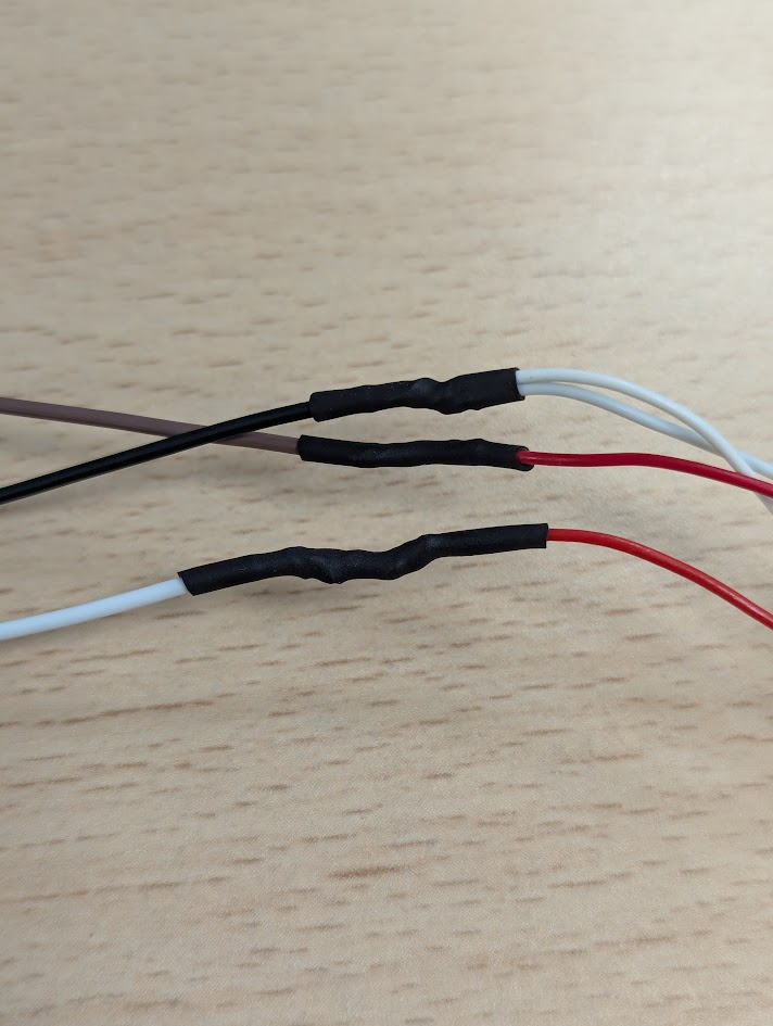
4 | Make sure to protect each connection to avoid electrical short circuits on the installation. |
|
5 | Plug the IOX-COLD to its cold chain harness’ 22 position connector. |
|


Door sensors
Door sensors detect the status of the trailer doors (open or closed) to help track and troubleshoot temperature delivery during transport.
The IOX-COLD can be connected to up to two door sensors.
Installation instructions
1 | After installing door sensors on the trailer, route their wiring to the IOX-COLD. | |
2 | Connect one pole of the magnetic switch to the IOX-COLD cold chain harness’ black loose wire. |
|
If the vehicle contains a second door sensor, connect one pole of the second door sensor to the same IOX-COLD cold chain harness Black loose wire. |
| |
3 | Connect the door sensor other pole to the IOX-COLD cold chain harness White loose wire. |
|
If the vehicle contains a second door sensor, connect the other pole of this second door sensor to the same IOX-COLD cold chain harness Brown loose wire. |
| |
4 | Make sure to protect each connection to avoid electrical short circuits on the installation. |
|
5 | Plug the IOX-COLD into its cold chain harness. |
|


Accessory wiring overview
This table summarizes the previous accessory connections.
Cold chain harness loose wires | Door sensors | 1-wire temperature sensors (up to 4 in parallel) | ||
Signal | Wire color | Wiring | Wiring | |
Inputs Ground Signal | Black | Main and secondary doors (doors 1 & 2) first poles. | ||
Main Input signal | White | Main door (door 1) second pole | ||
Secondary Input signal | Brown | Secondary door (door 2) second pole | ||
1-Wire Ground | Green | Red wire, VCC | ||
Black wire, GND | ||||
1-Wire Signal | Grey | Yellow wire, data | ||
IOX-COLD RUGGED
Cold chain solution installation - refrigeration unit
Typical installation connection schematic
The following schematic depicts a typical installation, with the required refrigeration unit harness depending on the make, model, and controller. Refer to the Cold Chain Harness Compatibility document to determine which harness is required for your particular situation.

Installation instructions
Manufacturer | Refrigeration Unit Model or Controller | Installation Instructions Document |
Thermo King | Smart Reefer 2 (SR-2) | |
Smart Reefer 3 (SR-3) | ||
Smart Reefer 4 (SR-4) | ||
Thermoguard V controller (TG-V) | ||
Thermoguard P P-IV controller (P P-IV) | ||
Thermoguard uP-IV multi-temp controller | ||
Thermoguard uP-V controller (uP-V) | ||
Thermoguard VI controller (TG-VI) | ||
Thermoguard uP-VI controller (uP-VI) | ||
Carrier Transicold | Vector/Ultra/Maxima | |
Carrier Transicold | X2100A | |
Carrier Transicold | APX |
Cold chain installation - accessories
Typical installation connection schematic
The following schematic depicts a typical installation, with the required refrigeration unit harness depending on the make, model, and controller. Refer to the Cold Chain Harness Compatibility document to determine which harness is required for your particular situation.

Preparing for installation
Ensure that you have all of the following:
Tools
|
Components
Product | Reference | Quantity |
IOX-COLD | IOX-COLD RUGGED | 1 |
Accessories interface harness | HRN-RCCAC | 1 |
1-wire temperature sensors
1-wire temperature sensors allow you to register temperature values in vehicles without connecting to a thermograph.
It is possible to connect up to 3 temperature sensors in parallel.
Installation Instructions
1 | After installing temperature sensor(s) on the trailer, route their wiring to the IOX-COLD RUGGED. | |
2 | Connect the Red and Black sensor wires to the harness’ HRN-RCCAC Green loose wire. |
|
3 | Connect the Yellow sensor wire to the harness’ HRN-RCCAC Grey loose wire. |
|
4 | Make sure to protect each connection to avoid electrical short circuits on the installation. |
|
5 | Plug the IOX-COLD RUGGED into the HRN-RCCAC harness. |
|


Door sensors
Door sensors detect the status of the trailer doors (open or closed) to help track and troubleshoot temperature delivery during transport.
The IOX-COLD RUGGED can be connected to up to two door sensors.
Installation instructions
1 | After installing door sensor(s) on the trailer, route their wiring to the IOX-COLD RUGGED. | |
2 | Connect one pole of the magnetic switch to the harness HRN-RCCAC Black loose wire. |
|
If the vehicle contains a second door sensor, connect one pole of this second door sensor to harness HRN-RCCAC Black loose wire. |
| |
3 | Connect the door sensor other pole to the harness HRN-RCCAC White loose wire. |
|
If the vehicle contains a second door sensor, connect the other pole of this second door sensor to the HRN-RCCAC Brown loose wire. |
| |
4 | Make sure to protect each connection to avoid electrical short circuits on the installation. |
|
5 | Plug the IOX-COLD RUGGED into the HRN-RCCAC harness. |
|


Accessory wiring overview
This table summarizes the previous accessory connections.
HRN-RCCAC loose wires | Door sensors | 1-wire temperature sensor | ||
Signal | Wire color | Wiring | Wiring | |
Inputs Ground Signal | Black | Main and secondary (Door 1 & 2) doors first poles. | ||
Main Input signal | White | Main door (Door 1) secondary pole | ||
Secondary Input signal | Brown | Secondary door (Door 2) secondary pole | ||
1-Wire Ground | Green | Red wire, VCC | ||
Black wire, GND | ||||
1-Wire Signal | Grey | Yellow wire, data | ||
Important Safety Information and Limitations of Use
For the latest version of the Limitations of Use, please visit: goo.gl/k6Fp0w.
WARNING! Do not attempt to install, configure or remove any product from any vehicle while the vehicle is in motion or otherwise in operation. All installation, configuration or removal must be done only in stationary vehicles which are securely parked. Attempting to service units while being operated could cause malfunctions or accidents, leading to death or serious personal injury.
WARNING! All in-vehicle devices and related cabling must be securely fastened and kept clear of all vehicle controls, including accelerator, brake and clutch pedals. You must inspect devices and cabling on a regular basis to ensure that all devices and cabling continue to be securely attached. Loose cabling or devices may impede the use of vehicle controls, resulting in unanticipated acceleration, braking or other loss of vehicle control, which could lead to death or serious personal injury. Improperly fastened in-vehicle devices may detach and impact operators upon sudden acceleration or deceleration, which may cause injury.
WARNING! If, at any point after an in-vehicle device is installed, a warning light illuminates on the vehicle dashboard or the vehicle stalls or has a marked drop in performance, shut off the engine, remove the device and contact your reseller. Continuing to operate a vehicle with these symptoms can cause loss of vehicle control and serious injury.
WARNING! Your in-vehicle devices must be kept clear of debris, water and other environmental contaminants. Failure to do so may cause units malfunctioning or short-circuiting, which can lead to a fire hazard or vehicle damage or serious injury.
WARNING! Do not attempt to remove the devices from the vehicle they were originally installed in for installation in another vehicle. Not all vehicles share compatibility, and doing so may cause unexpected interactions with your vehicle, including sudden loss of power or shutdown of the vehicle's engine while in operation or cause your vehicle to operate poorly or erratically and cause death or serious injury and/or vehicle damage.
NOTICE: This product does not contain any user-serviceable parts. Configuration, servicing and repairs must only be made by an authorized Reseller or installer. Unauthorized servicing of these products will void your product warranty.

