IOX-WRKS: Winter Solution Sensor Mounting
Installation Guide
4 mins to read
Learn the best practices for the placement and installation of sensors used in the IOX-WRKS solution, including front and side plow sensors, loader lift arm sensors, grader molder sensors, sidewalk vehicle sensors, and hydraulic sensors.
Winter Solution Sensor Mounting
This guide provides instructions and best practices for the placement and installation of various sensors used in Winter Operations fleets. Additional related information can be found in these documents:


Sensor mounting and placement
Prior to any install, consult with the client for their guidance in selecting sensor mounting locations that meets the needs of the installation. Ensure the location provides the necessary telemetry, operational needs, servicing access, and most importantly, protection from corrosion and damage.
Mounting sensors typically involves welding or hydraulics. Attempting to perform these operations without proper training and knowledge can lead to injury or death. Please obtain professional installation services from trained technicians with welding and/or hydraulic certification.
When mounting sensors, it is the client’s responsibility to provide direction and support to ensure that the sensors are mounted in optimal locations that do not interfere with normal maintenance and operation. It is advisable to always mount proximity sensors perpendicular to the moving equipment so that the sensor does not get impacted or damaged.
Sensors should always be configured to be active when the equipment is being operated. An example would be active when the plow is down, or active when the manual spreader is actively applying material. This configuration helps reduce telemetry errors, and maintains uniformity in winter operations reports.
|
|
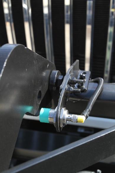
Hydraulic sensor – sensitivity range of 100-1500 PSI, which can be adjusted by twisting the central shaft (see arrow). | Proximity sensor – when powered, will detect metallic objects within ~1/2” from the sensor, depending on make and model. The LED indicator (see arrow) glows when metal is detected, used for diagnosis and calibration. |


Powering the sensor
Depending on the make and model, a proximity sensor will draw ~200 mA when activated. For this reason, all sensors must be powered from an ignition source. Preventing battery drain is a constant and necessary concern.
Note: The IOX-WRKS provides a +12V (max 650mA) and ground source for powering sensors, when the vehicle is running. To use this feature, it requires activation at the time of configuration. Do not connect these wires to vehicle power or ground.
Mounting sensors
When welding or a hydraulic connection is required, it is the client’s responsibility to procure or provide professional installation services.
The remaining pages show examples of mounting locations on various types of vehicles.
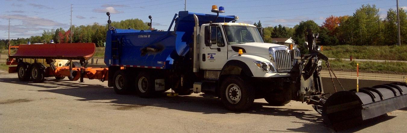
Front plow sensor mounting
|
| |
|
| |
The sensor should read ON when the plow is down.
|
| |


For a video about sensor installation, refer to the following link: Front Plow Proximity Sensor Installation
Wing plow sensor mounting
|
|
| ||
|
|
| ||
The sensor should read ON when the wing is down. |
|
| ||


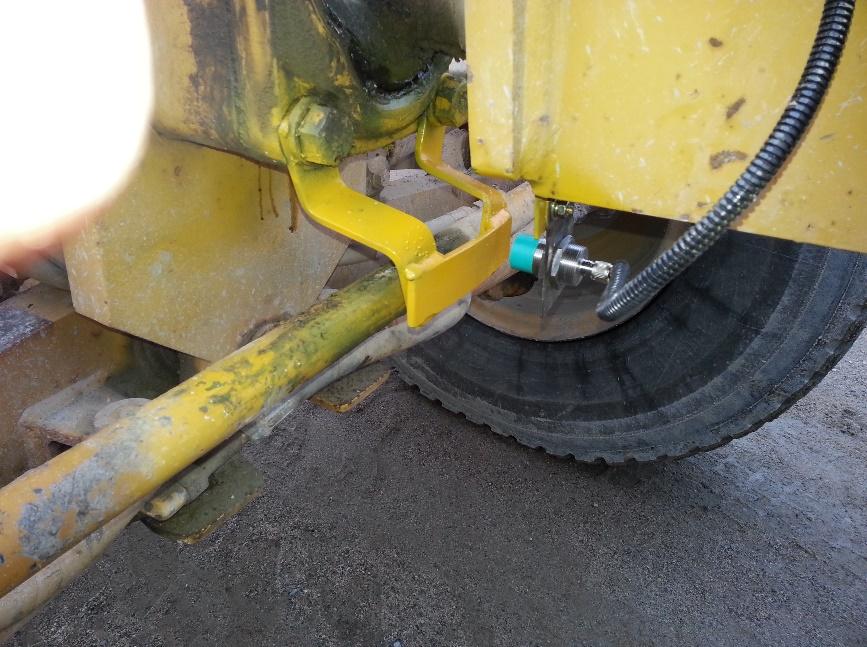
Loader lift arm sensor mounting
|
|
| ||
|
|
| ||
|
The sensor should read ON when the arm is down. |
| ||


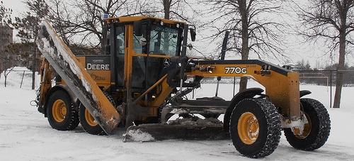
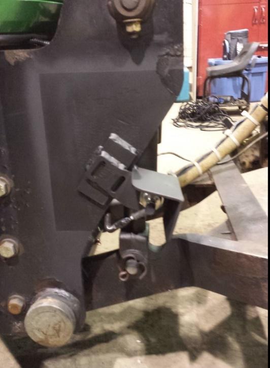
Grader moldboard sensor mounting with custom built bracket
|
| |
The sensor should read ON when the blade is down. |
| |

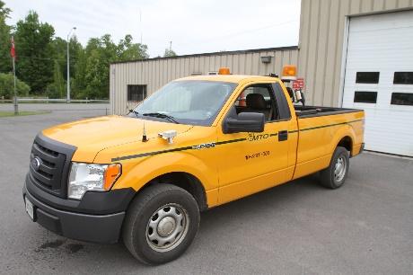
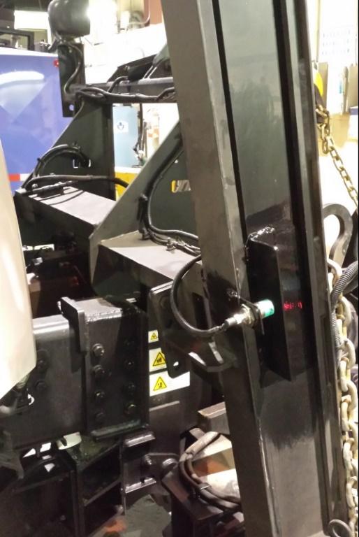
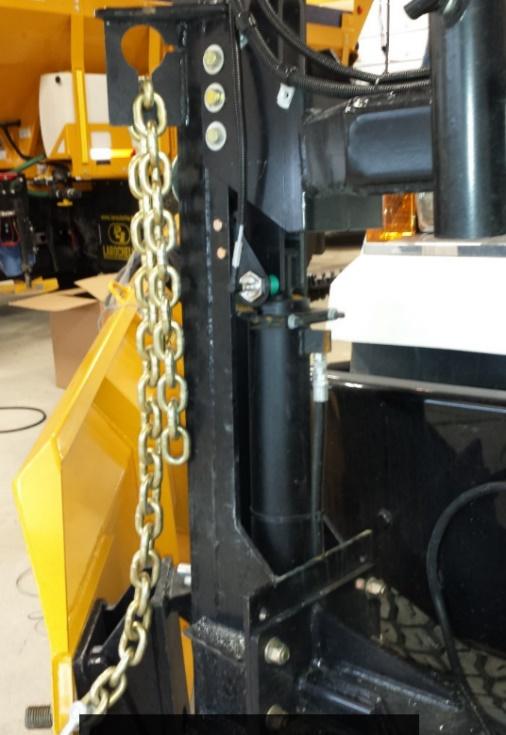
Sidewalk vehicle sensor mounting with custom built bracket
|
| |
|
| |
|
| |
The sensor should read ON when the lift arm/blade/blower/broom is down. |
| |

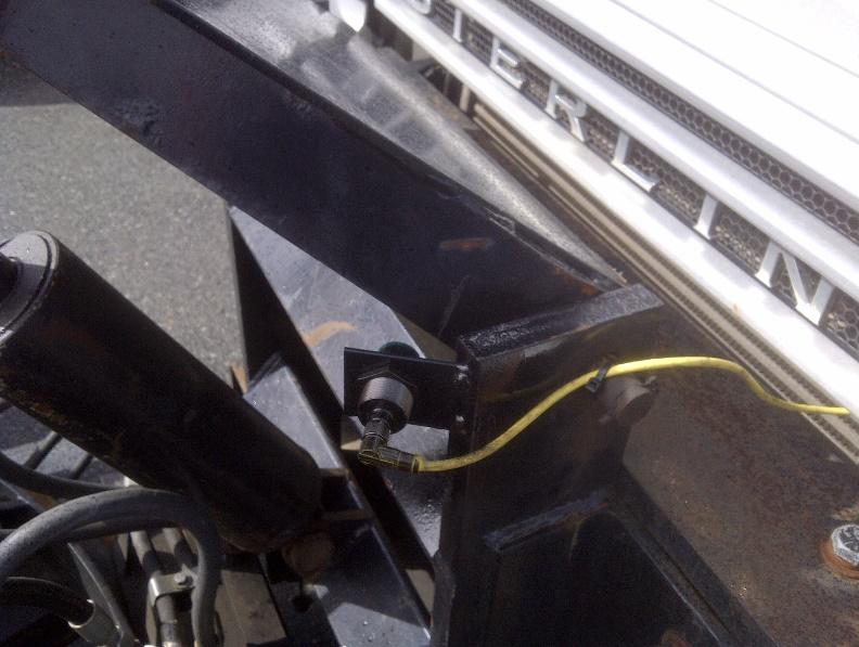
Hydraulic sensors
The primary reason for using a hydraulic sensor should be to detect activation of a hydraulic motor used on conveyors, augers or spinners. If a material application is being monitored, it is advisable to monitor the component that “must” move for material to be applied. For instance, a typical manual spreader may have a conveyor to move material to a chute where it drops to a spinner. In this case, the conveyor is the function best monitored, as material cannot be applied without the conveyor moving.
Usually, a proximity sensor is a better option for monitoring lift arms or plow position. Some exceptions do apply where a proximity sensor would be too difficult to mount, or subjected to excessive damage. This would include a belly mounted plow or the wing plow on graders. In some cases, the client may have a sensor preference, which will determine your telemetry capturing options.
Professional certified hydraulic installation is required. Attempting to perform these operations without proper training and knowledge can lead to injury or death.
|
| |
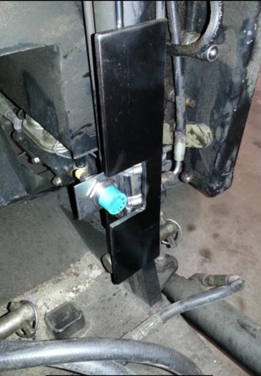
The hydraulic manifold is usually the best mounting location for hydraulic sensors. The sensor is closed when operation is active. |
| |
|
| |
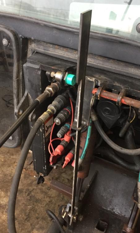
Mounting the hydraulic sensor at the piston usually exposes the sensor to a harsher environment with a higher likelihood of damage, and can require cable lengthening. Because of this, try to avoid mounting the sensor at these locations whenever possible. Always avoid grounding the sensor at these locations. |
| |


Manual material spreader – sidewalk unit
|
| |
Mounting example for a sidewalk manual spreader – sensor installed to monitor hydraulic motor on/off. |
| |


