T-Harness For GO Device — 9-pin Universal Heavy-Duty
Support Document
0 mins to read
Connect a GO device to your heavy-duty vehicle using a HRN-GS09K2 harness. The Deutsh T-Harness is used to connect a GO device to most heavy-duty vehicles internationally and contains four mounting adapters engraved with numbers for easy reference.
For the most up to date version, please visit: gtb.link/Z4sUe
The HRN-GS09K2-A, a Deutsch T-harness kit with four mounting brackets, connects a Geotab® GO device to most international heavy-duty vehicles. The HRN-GS09K2-A contains four mounting adapters, engraved with numbers for easy reference. The adapters are named as follows:
- Flange & Screw Mount;
- Flange & Screw Mount Extended;
- Flange and Thread Mount + Nut; and
- Thread Mount + Nut.
! IMPORTANT: USA Only: Place the enclosed CARB Executive Order (EO) identification label sticker in the vehicle engine compartment, somewhere near the Vehicle Emission Control Information label on a smooth and clean surface. The EO identification label is required to aid inspection of the vehicle under the California Smog Check program and other applicable smog test programs. See here for more info.
Harness Technical Specifications
Weight | 140 g |
Size | Max Length: 685 mm Max Width: 47.8 mm |
Material | Universal 9-pin connectors: Polycarbonate, Nylon, Silicone (rubber) Adapters: Polycarbonate Universal 16-pin connector: PBT Wire Jacket: Mesh Sheathing |
Connectors | 2 × Universal Deutsch Connectors 1 × 24 V compatible ALDL Connector |
Power Output | 8 V to 36 V |
Current Rating | 5 A |
Temperature Rating | −40 to +85 °C |
Adapters | See Adapters Below |
WARNING! The HRN-GS09K2-A harness kit is designed and intended for use only with the GO device or Geotab-authorized accessory devices. Professional installation from a Geotab Authorized Installer is required. Read and follow the complete GO device installation instructions (gtb.link/i8JX) as well as these installation instructions to prevent serious personal injury or significant damage to your vehicle.
Adapters
1 |
| 2 |
|
Flange & Screw Mount | Flange & Screw Mount Extended | ||
3 |
| 3N |
|
Flange & Thread Mount | Flange & Thread Mount Nut | ||
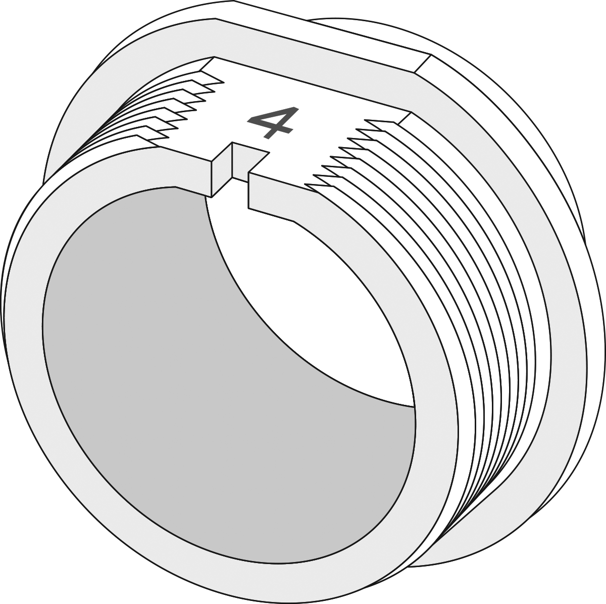
4 |
| 4N |
|
Thread Mount | Thread Mount Nut |


Harness Installation Instructions
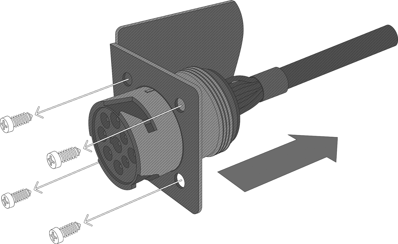
1 | Unplug the GO device from the vehicle and remove the in-vehicle diagnostic connector from its bracket. ✱ NOTE: Not all heavy-duty vehicles use the same connection system for securing the in-vehicle diagnostic connector to the bracket. Always follow the manufacturer's suggested method of installation, or removal, for any connector and bracket. |
|
2A | Insert the HRN-GS09K2-A male harness connector into the vehicle bracket and secure it in place (using the appropriate connection method). If you are securing the adapter with screws, this method will apply to both Adapter 1 and Adapter 2. ✱ NOTE: Adapter 1 is pre-installed on the male harness connector. Always use the adapter that matches the diagnostic connector shape of your vehicle. For steps on how to change the adapter, see the Changing Adapters section below. |
|
2B | For heavy-duty vehicles that require Adapter 3 or Adapter 4, the male connector is secured inside the vehicle bracket using the 3N and 4N nuts supplied in the HRN-GS09K2-A kit. The nuts are NOT interchangeable and only used with their corresponding adapters. |
|
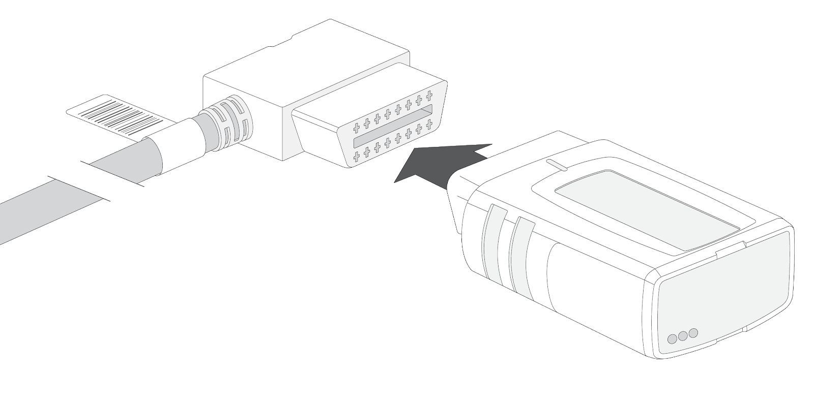
3 | Connect the GO device to the female universal 16-pin connector (long end) of the harness. |
|
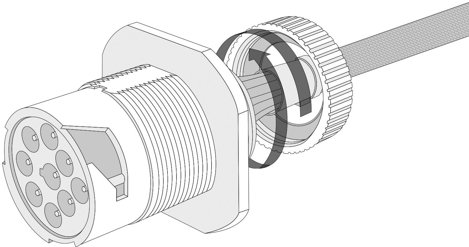
4 | Connect the in-vehicle diagnostic connector to the HRN-GS09K2-A harness female connector. Lock the connection using the locking ring on the harness female connector. |
|
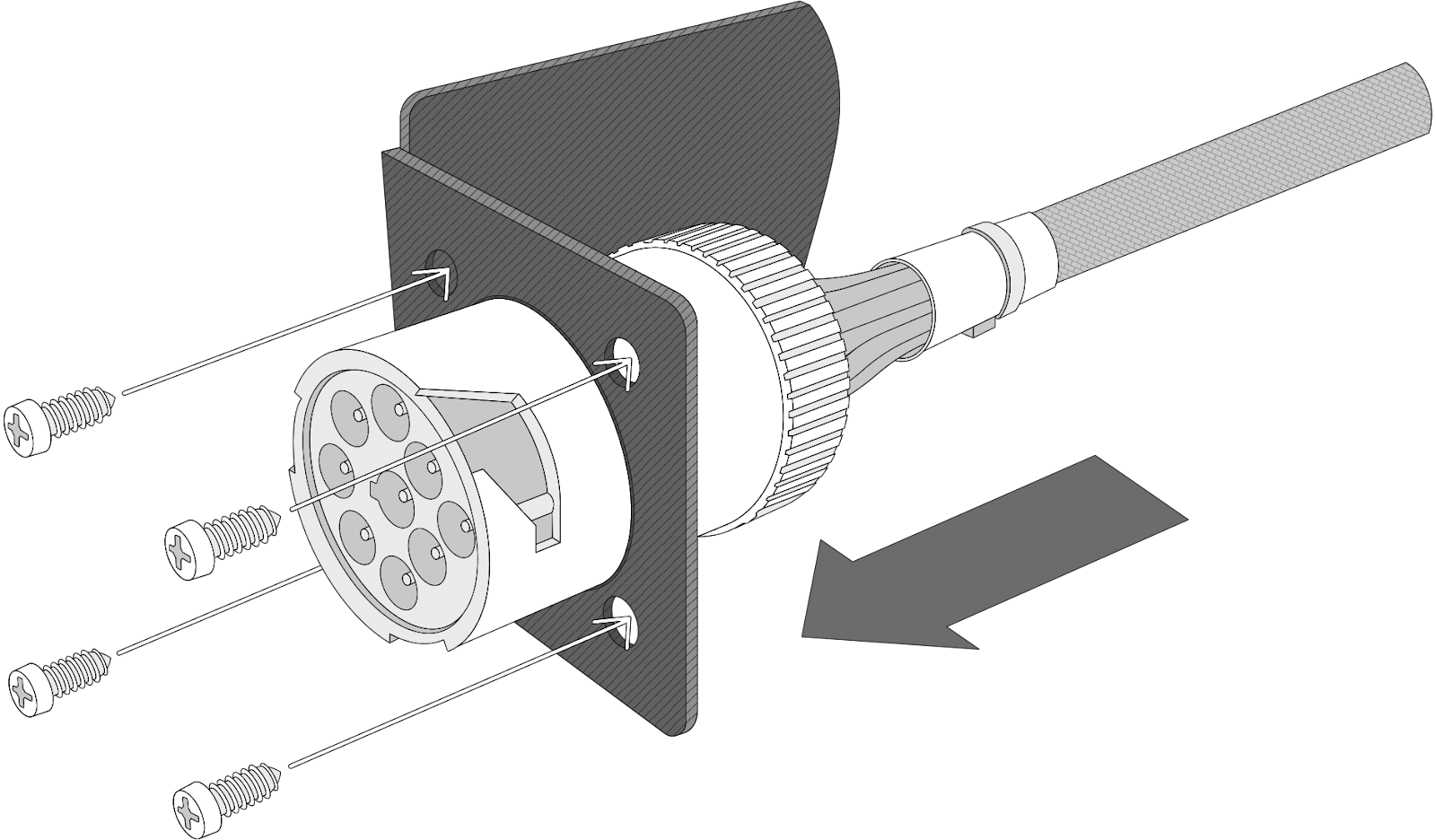


Completed Setup
Changing Adapters
If your vehicle does not use the pre-installed Adapter 1, follow the steps below to replace it with the required adapter. There are no special tools needed to change the adapter.
✱ NOTE: Ensure the harness is disconnected from the vehicle before changing the adapter.
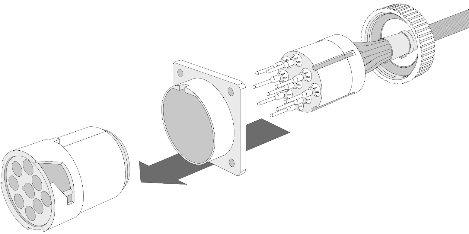
1 | On the HRN-GS09K2-A male harness connector, remove the screw cap at the back of the connector and slide it slightly away from the connector. |
|
2 | Slide the connector forward and off the terminal cartridge. Please ensure that you do not damage or move the 9 terminals inside. This will make re-insertion into the male connector easier. |
|
3 | Hold the connector and pull the adapter (Adapter 1 in this case) backwards and off the male connector. |
|
4 | Insert the desired adapter into the male connector once again. Ensure that the adapter is correctly oriented so as to slide into the notch on the male connector. |
|
5 | Move the male connector back onto the terminal cartridge carefully and line up the two installation slots on the side of the terminal cartridge with the notches inside the male connector. |
|
6 | Screw the cap back on at the back of the connector. Please ensure the connection is tight and that there is no gap between the adapter and the screw cap. |
|


Important Safety Information and Limitations of Use
For the latest version of the Limitations of Use, please visit: gtb.link/k6Fp0w
WARNING! Do not attempt to install, configure or remove any product from any vehicle while the vehicle is in motion or otherwise in operation. All installation, configuration or removal must be done only in stationary vehicles which are securely parked. Attempting to service units while being operated could result in malfunctions or accidents, leading to death or serious personal injury.
WARNING! All in-vehicle devices and related cabling must be securely fastened and kept clear of all vehicle controls, including gas, brake and clutch pedals. You must inspect devices and cabling on a regular basis to ensure all devices and cabling continue to be securely attached. Loose cabling or devices may impede the use of vehicle controls, resulting in unanticipated acceleration, braking or other loss of vehicle control, which could lead to death or serious personal injury. Improperly fastened in-vehicle devices may detach and impact operators upon sudden acceleration or deceleration, which may cause injury.
WARNING! If at any point after an in-vehicle device is installed a warning lights up on the vehicle dash or the vehicle stalls or has a marked drop in performance, shut off the engine, remove the device, and contact your reseller. Continuing to operate a vehicle with these symptoms can cause loss of vehicle control, and serious injury.
WARNING! Your in-vehicle devices must be kept clear of debris, water and other environmental contaminants. Failure to do so may result in units malfunctioning or short-circuiting that can lead to a fire hazard or vehicle damage or serious injury.
WARNING! Do not attempt to remove the devices from the vehicle in which they are originally installed for installation in another vehicle. Not all vehicles share compatibility, and doing so may result in unexpected interactions with your vehicle, including sudden loss of power or shutdown of the vehicle’s engine while in operation or cause your vehicle to operate poorly or erratically and cause death or serious injury and/or vehicle damage.
NOTICE: This product does not contain any user-serviceable parts. Configuration, servicing, and repairs must only be made by an authorized reseller or installer. Unauthorized servicing of these products will void your product warranty.

