IOX-COLD — Tachograph Solution Installation Guide
Support Document
0 mins to read
IOX-COLD allows the GO device to read and download real-time data from digital tachographs. This data can then be viewed and analyzed in the Geotab Tachograph Module for the MyGeotab platform.
Tachograph Solution Installation Guide
Introduction
IOX-COLD allows the GO™ device to read and download real-time data from digital tachographs. This data can then be viewed and analyzed in the Geotab Tachograph Module for the MyGeotab™ platform.
! IMPORTANT: IOX-COLD is compatible with all tachograph brands. However, the tachograph itself must support remote download (RDL) functionality. For more information, refer to the Remote Download (RDL) Capability section.
! IMPORTANT: Once the required installations between the IOX-COLD and its compatible solutions (Refrigeration unit and accessories, Thermograph, Tachograph, Expansions) have been completed, the IOX-COLD must be installed with GO9 devices as outlined in the quick start guide.
Access to the quick start guide documents here: gtb.link/ioxcold
Pre-installation steps
Tachograph connections
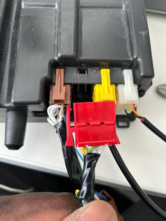
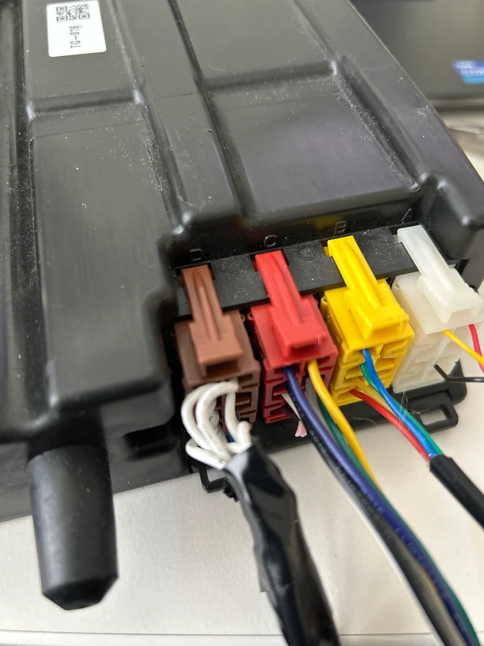
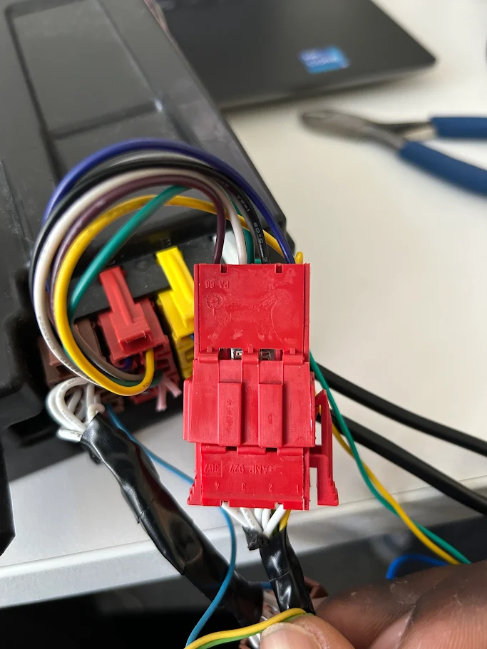
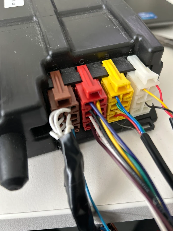
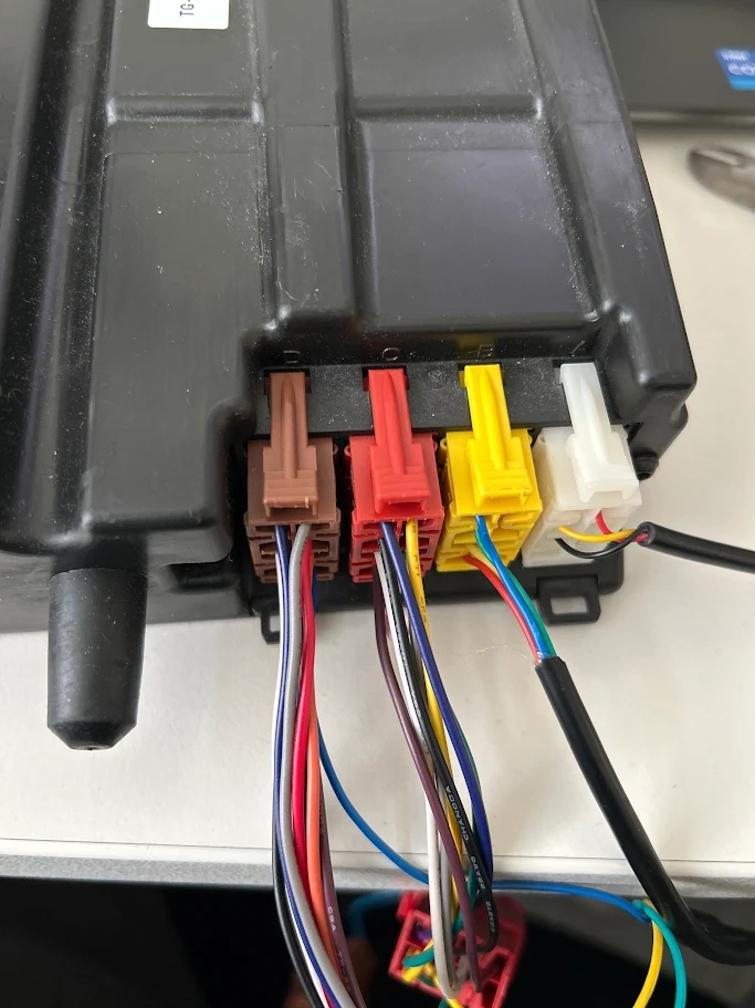
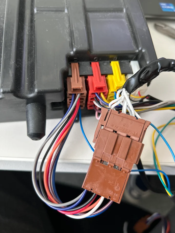
Tachographs have four ports: A (WHITE), B (YELLOW), C (RED), and D (BROWN).
✱ NOTE: The four ports are mechanically polarized/keyed and will only fit into appropriate mating receptacles. Do not force while fitting the connector.

✱ NOTE: Some tachographs are protected with a security seal that must be removed to proceed with the installation.
|
|


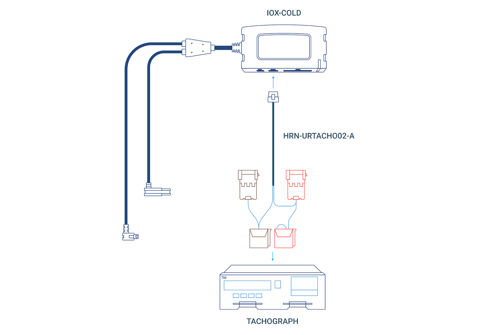
Typical installation connection schematic
Preparing for installation
Ensure that you have all of the following materials:
Tools
- Screwdriver kit
- Cable guide
- Cutter plier
- Gripping plier
- Tachograph/thermograph extractor keys
- Cable ties
Components
Product | Reference | Remarks |
IOX-COLD | IOX-COLD | Required for all installations |
Tachograph connections harness ✱ NOTE: This harness must be requested by the Partner for projects with digital tachograph connections. | Required for all installations | |
Harness for VDO tachograph frontal connector | Only required if a frontal connection to the tachograph is necessary |
Warnings and important notes
✱ NOTE: If installing in a Scania vehicle and the C connector (RED) already has wires connected to C5 and C7, and there are no wires connected to A4 and A8, see Scania Vehicles with Tachograph SRE6.x before installation.
! IMPORTANT: Do not modify the provided C connector (RED). This connection cannot be shared, and there must never be multiple connections as this can cause interferences in the vehicle CAN bus, which could cause malfunctions.
WARNING! If, at any point, a warning light illuminates on the vehicle dashboard or the vehicle stalls or has a marked drop in performance, shut off the engine, remove the device and contact Support. Continuing to operate a vehicle with these symptoms can cause loss of vehicle control and serious injury.
! IMPORTANT: After extracting the Tachograph, be very careful when leaving the tachograph hanging to avoid any cable damage.
WARNING! We strongly recommend you do not create any electrical connection (vehicle harness modification, splices etc.) between Geotab devices (GO9 + IOX-COLD) and tachograph ports A and B (for example, power supply through the 3-wire harness or CAN bus connection). The Geotab Truck Solution is not designed to interface with these ports, and Geotab is not responsible for any mechanical, electrical, or legal issues caused by a connection made to tachograph ports A and B.
Installation instructions
There are many installation scenarios (for example, installation instructions are different if the tachograph’s port C is in use or not), but the high-level steps are as follows. Click the links below to jump to each section.
- Unmounting the tachograph
- Connecting the remote download to tachograph port C (several different installation scenarios - see substeps):
- Tachograph port C is available
- Tachograph port C is in use by a DSRC antenna and/or OEM device
- Measuring the CAN termination resistance (to determine the appropriate installation procedure)
- CAN termination resistance is ~120 ohms
- CAN termination resistance is ~60 ohms or less
- CAN termination resistance is well above 120 ohms
- Installation for VDO tachographs version 1.2 or older
- Installation in Scania vehicles that have had, or currently have, an SR6.x tachograph installed
- Installing the real-time data connection to tachograph port D (three different installation scenarios - see substeps):
- Connecting the harness to the IOX-COLD
- Installing the GO device and validating the installation
- Finishing steps
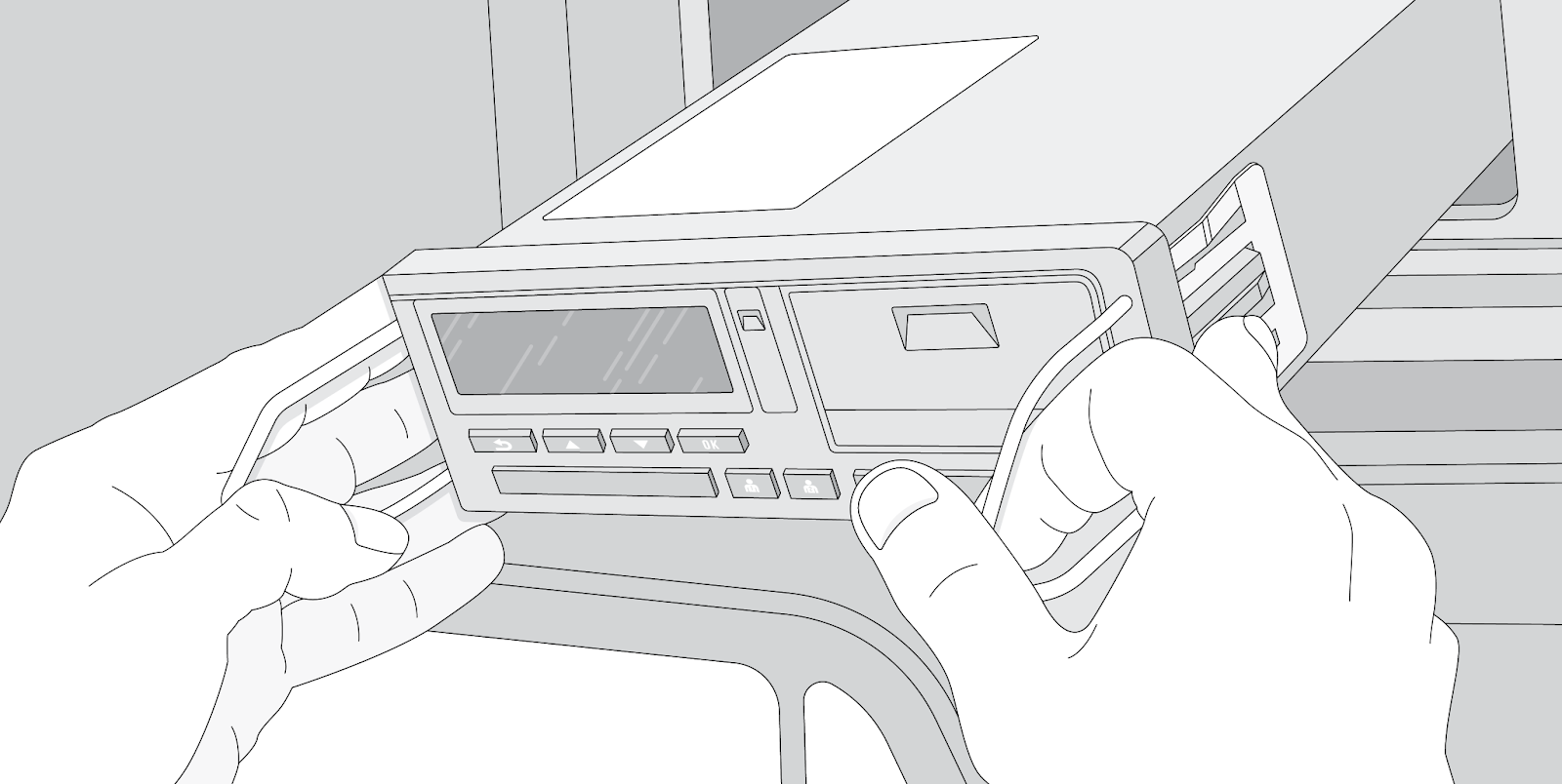
Unmounting the tachograph
Remove the tachograph from its slot using extractor keys:

Connecting the remote download (tachograph port C)
This connection is made to the CAN bus Port-C of the tachograph. Only the C5 (CAN-H signal) and C7 pins (CAN-L signal) are used by the IOX-COLD. The CAN bus Port-C of a tachograph is also known as CAN-C, CAN2 or CAN-FMS.
This section covers various installation scenarios. Refer to whichever section that applies to your specific situation and then proceed to Installing the real-time data connection afterwards:
- Tachograph port C is available
- Tachograph port C is in use by a DSRC antenna and/or OEM device - first measure the CAN termination resistance to determine the correct configuration:
- Installation for VDO tachographs version 1.2 or older
- Installation in Scania vehicles that have had, or currently have, an SR6.x tachograph installed
Scenario 1: tachograph port C is available
If the tachograph port C is available, connect the red connector of the HRN-URTACH02-A to this port:

Once this is done, proceed to Installing the real-time data connection.
If this is not your installation use case, skip this step and see the next installation steps until you find yours.
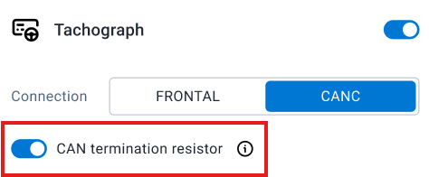
! IMPORTANT: In this case, while running MyInstall, make sure you enable the CAN termination resistor toggle:
Scenario 2: tachograph port C is in use by a DSRC antenna and/or OEM device
This section covers the installation method for tachographs where the port C is already in use.


If this is not your installation use case, skip this step and see the next installation steps until you find yours.
! VERY IMPORTANT: When measuring/troubleshooting CAN-C termination or remote tachograph download failures, if present, the vehicle's factory OEM telematics device must be identified and isolated.
- DO NOT disconnect the main CAN-C connector (if present), as this will kill the power/signal to the mandatory DSRC remote enforcement antenna.
- Manually locate the specific OEM device wire split and disconnect ONLY the OEM device.
- The DSRC antenna must always remain connected. This means that only the Geotab solution or the OEM solution can be connected to the Tachograph CAN-C interface.
Measuring the CAN termination resistance
To determine the correct installation method, you’ll need to measure the CAN termination resistance.
Using a multimeter in ohmmeter mode, measure the CAN termination resistance between pins 5 and 7 of the tachograph’s port C.
! VERY IMPORTANT: While measuring, ensure that the vehicle ignition is off and that you do not disconnect or modify any of the existing tachograph connections:

Based on the ohmmeter measurement, refer to the appropriate section for connection instructions:
- Scenario 2a: CAN termination resistance is around 120 ohms
- Scenario 2b: CAN termination resistance is around 60 ohms or less
- Scenario 2c: CAN termination resistance is well above 120 ohms
Scenario 2a: CAN termination resistance is around 120Ω
If tachograph port C is already in use and the measured termination resistance is around 120 ohms, here’s how to connect the remote download:
- Cut the pink jumper on Connector C (red) of HRN-URTACHO02-A, between pins C7 and C8.


- Remove the existing connection from port C of the tachograph:
- Connect the red connector on HRN-URTACHO02-A to port C of the tachograph:
- Plug in the original connection (that you removed in step 2) to the other red connector of HRN-URTACHO02-A:

- ! IMPORTANT: While running MyInstall, make sure you enable the CAN termination resistor toggle:

Once this is done, proceed to Installing the real-time data connection.
If this is not your installation use case, skip this step and see the next installation steps until you find yours.
Scenario 2b: CAN termination resistance is around 60 ohms or less
If tachograph port C is already in use and the measured termination resistance is around 60 ohms or less, here’s how to connect the remote download.
✱ NOTE: If the measured value is below 40 ohms, data transmission on the bus might be incomplete due to an excess of CAN termination resistors on the CAN bus. In such instances, we recommend taking the vehicle to a workshop for troubleshooting and to determine if all pre-installed termination resistors are necessary.
- Cut the pink jumper on Connector C (red) of HRN-URTACHO02-A, between pins C7 and C8:


- Remove the existing connection from port C of the tachograph:

- Connect the red connector on HRN-URTACHO02-A to port C of the tachograph:

- Plug in the original connection (that you removed in step 2) to the other red connector of HRN-URTACHO02-A:
- ! IMPORTANT: While running MyInstall, make sure you disable the CAN termination resistor toggle:

Once this is done, proceed to Installing the real-time data connection.
If this is not your installation use case, skip this step and see the next installation steps until you find yours.
Scenario 2c: CAN termination resistance well above 120 ohms
If tachograph port C is already in use and the measured termination resistance is well above 120 ohms, here’s how to connect the remote download:
- Disconnect the vehicle’s connector from the port C of the tachograph:

- Connect the red connector on HRN-URTACHO02-A to port C of the tachograph:
- Connect the vehicle’s connector to the other red connector of HRN-URTACHO02-A:

- ! IMPORTANT: While running MyInstall, leave the CAN Termination resistor activated:

Once this is done, proceed to Installing the real-time data connection.
If this is not your installation use case, skip this step and see the next installation steps until you find yours.
Scenario 3: Installation for VDO tachographs version 1.2 or older
Here’s how to make the remote download connection if the vehicle has a VDO tachograph version 1.2 or older:
- Cut the pink jumper on Connector C (red) of HRN-URTACHO02-A, between pins C7 and C8:


- If port C of the tachograph is already being used, then disconnect that connector and leave it tidied up with the rest of the cables:

- Connect the red connector of HRN-URTACHO02-A to Port C of the tachograph:

- ! IMPORTANT: Do not modify the provided C connector (red). This connection cannot be shared, and there must never be multiple connections as this CAN bus causes interferences in the vehicle CAN bus, which could cause malfunctions.
- ! IMPORTANT: While running MyInstall, make sure you enable the CAN termination resistor toggle:

Once this is done, proceed to Installing the real-time data connection.
If this is not your installation use case, skip this step and see the next installation steps until you find yours.
Scenario 4: Installation in Scania vehicles that have had, or currently have, an SR6.x tachograph installed
This is a special case for all Scania vehicles which previously had or currently have a Stoneridge 6.x tachograph. Usually in those installations, tachographs have been or will be replaced with a newer model without modifying the electrical installation.
First, check the connectors A and C. This operation only applies if the vehicle is a Scania with a Stoneridge tachograph with the vehicle CAN bus connected to port C of the tachograph. This situation is easy to diagnose as there are no wires connected to A4 and A8.
Before connecting the HRN-URTACHO02-A, make the following modifications as instructed in Stoneridge information bulletin NT2009/012:

- Remove wires from connector C (red).
- Remove the C7 and C8 jumpers.
- Remove the wire in C5 and place it in A4.

- Remove the wire in C7 and place it in A8.

- Reconnect connector A (white) to the tachograph and continue with the installation.
- If you are replacing the tachograph with a more modern one, configure the tachograph as indicated by the manufacturer. If you are not replacing the tachograph, configure the tachograph using a diagnosis tool. Check the following parameters:
- Ilum.Input (0xFD15): 0 Disabled, 1 CAN, 2 A2. In case of doubt use 0, but do not use option 1.
- CAN bus Activ (0xFD1E): 1 Activated.
- CAN termination (0xFD5B): Activated if C7 and C8 are jumpered.
Once this is done, proceed to the next section.
Installing the real-time data connection (tachograph port D)
This connection is made to port D of the tachograph or via its frontal connector, only the D8 pin (K-LINE signal) is used by IOX-COLD.
The real-time data connection has the following installation scenarios:
- Tachograph port D is available
- Tachograph port D is in use by a brown connector
- Installation for VDO tachographs versions 1.3 and 1.4
Once you make the appropriate connection for your scenario, proceed to Connecting the harness to the IOX-COLD.
Scenario 1: tachograph port D is available
If the tachograph port D is available, connect the brown connector of the HRN-URTACHO02-A to this port.

Proceed to Connecting the harness to the IOX-COLD.
If this is not your installation use case, skip this step and see the next installation steps until you find yours.
Scenario 2: tachograph port D is in use by a brown connector
Here’s how to make the real-time data connection if port D is already in use by a brown connector:
- Disconnect the vehicle’s brown connector from port D of the tachograph:

- Connect the HRN-URTACHO02-A brown connector to port D of the tachograph:
- Connect the vehicle’s connector to the other brown connector on HRN-URTACHO02-A:
Proceed to Connecting the harness to the IOX-COLD.
If this is not your installation use case, skip this step and see the next installation steps until you find yours.
Scenario 3: real-time data connection for VDO tachographs versions 1.3 and 1.4
For some VDO tachographs, you will need additional parts to make the real-time data connection:
Product | Reference | Remarks |
VDO DTCO update card | N/A | Client-supplied |
Harness for VDO tachograph frontal connector | HRN-CL01S2 | Required |

- Enable Frontal Remote Download with the DTCO Update Card.
- Connect HRN-CL01S2 (C309) to the VDO Frontal Port

- Connect Harness HRN-CL01S2 (C309) to connector D (brown) of the HRN-URTACHO02-A:

- ! IMPORTANT: In MyInstall, make sure you select the Frontal connection in the tachograph section:

Proceed to Connecting the harness to the IOX-COLD.
Connecting the harness to the IOX-COLD
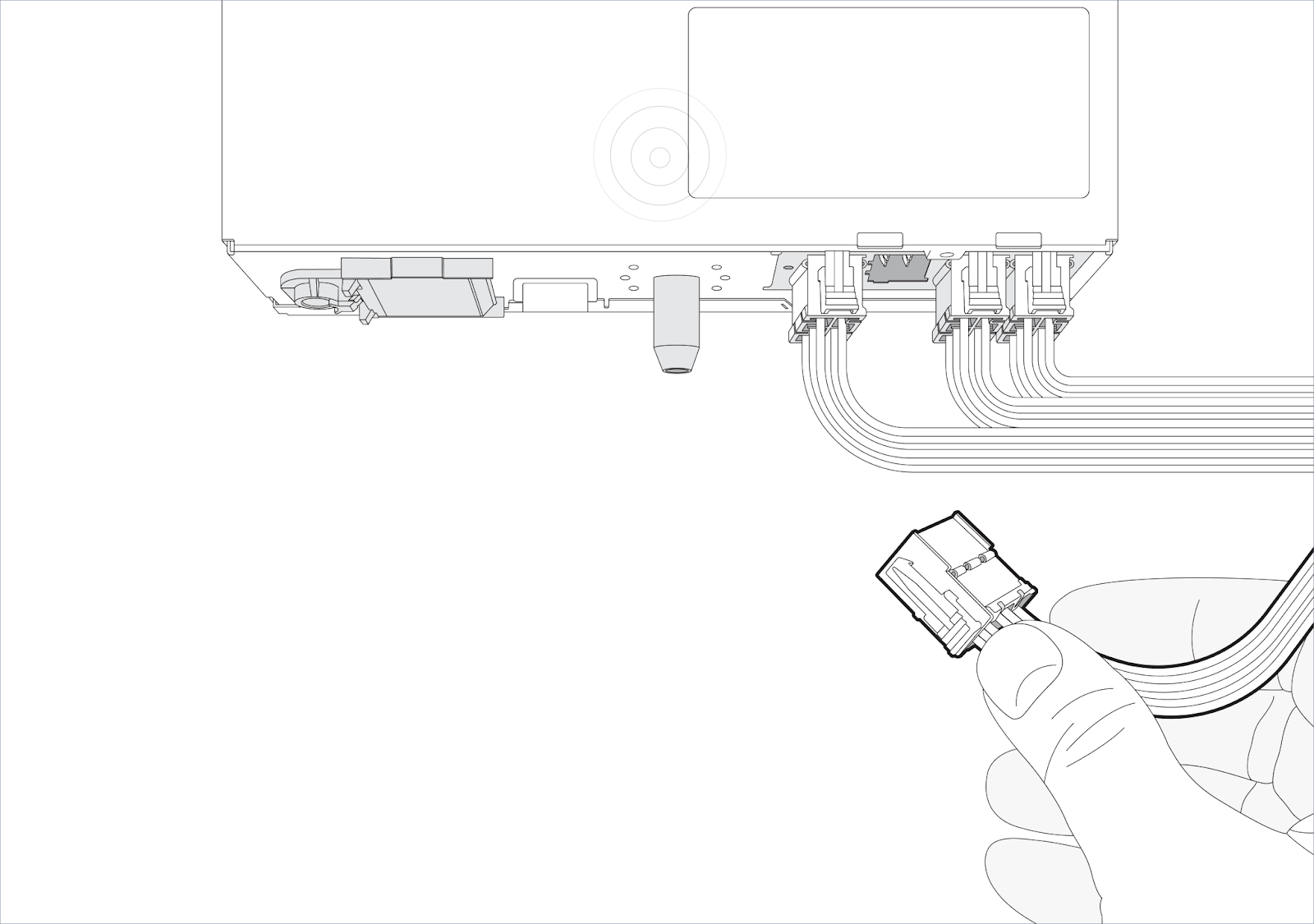
Next, route the HRN-UTACHO02-A harness from the tachograph to the IOX-COLD. Connect the harness’s 6-pin Molex connector to the IOX’COLD’s port B:

Installing the GO device and validating the installation
GO device installation
Once the harness routing and IOX-COLD cable connections have been made, install and connect them to the GO device. Refer to the quick start guide at the following link for full instructions: gtb.link/ioxcold
Validating the installation using MyInstall
! IMPORTANT: Using the MyInstall tool is mandatory for every installation to correctly configure the IOX-COLD and ensure accurate data is obtained.
You need a secure MyAdmin login to use this tool. If you do not have one, refer to the Creating MyInstall Credentials section of the MyInstall User Guide.
To determine whether to activate or deactivate the IOX-COLD CAN Termination on the MyInstall tool, consult the various port C installation scenarios.

Taking a CAN termination resistance measurement (recommended)
It is optional but recommended to take a CAN termination resistance measurement after all of the above has been done. The reason for this is that if the resistance deviates significantly from 60 ohms, you should double-check the port C installation scenarios.
- Using a multimeter in ohmmeter mode, measure the CAN termination resistance between pins 5 and 7 of the tachograph port C.

- ! VERY IMPORTANT: While measuring, ensure that the vehicle ignition is off and that you do not disconnect or modify any of the existing tachograph connections.
If the measured value deviates significantly from 60Ω, inspect the installation and confirm that all connections have been correctly implemented as per a Port-C installation scenario.
Finishing steps
Once everything is done, place back the tachograph in its slot.
Appendix
Remote download (RDL) compatibility
It is important to know if the tachographs in your fleet are compatible with the remote download system. Based on the brand of your tachographs, there are different ways to do this. Use the following tool to check the compatibility between a tachograph brand and Geotab tachograph solution: Online RDL Check Tool.
Stoneridge
All Stoneridge models support remote download from revision 7 (REV7).
✱ NOTE: The OK Rule: If there is an OK button, then it supports RDL. Check your tachograph keyboard symbols:
Supports remote download: | Does not support remote download: |
|
|


! IMPORTANT: Check with a calibration tool (MKII or similar) that the following parameters are activated:
- CAN bus Activ
- RD Act. status
- Config. RD CAN
Actia
 All Actia tachograph models that include the word REMOTE or have a reference number greater than or equal to 921871 support remote download. The reference number is on the tachograph sticker. To access the tachograph sticker, remove the tachograph from the packaging and look on both sides.
Siemens VDO
Most Siemens VDO models from version 1.3a support remote download. To confirm compatibility, navigate to Online RDL Check Tool and enter the Typ number. The Typ number is found on a sticker inside the printer compartment or in the Tachograph ticket, as shown below.
✱ NOTE: To access the tachograph sticker, you must open the printer and remove the paper roll.
|
|


! IMPORTANT: Use a calibration tool (CTCII or similar) to check that the following parameters are activated:
- CAN2 ON/OFF
- CAN2 Remote Download
EFAS
Remote download is available on model EFAS-4 with version 2.00–2.15 and higher. The model and version number can be found on your Tachograph label, placed in the lower side of the Tachograph or in the Tachograph ticket:
|
|


! IMPORTANT: Remote download must be activated using the EFAS Service Tool. The following parameters must be configured as indicated:
- FMS Activation is set to AUX-Bus,
- CAN Bus AUX CAN-C "Activation is set to ON,
- Length of Identifier is set to 29 [Bit],
- Bitrate is set to 250 [kBit/s],
- Transmission Rep Rate TC01 is set to 0 [ms], and
- VU wakeup via CAN AUX bus is set to ON (LCD:OFF).
Important safety information and limitations of use
WARNING! Do not attempt to install, configure or remove any product from any vehicle while the vehicle is in motion or otherwise in operation. All installation, configuration or removal must be done only in stationary vehicles which are securely parked. Attempting to service units while being operated could cause malfunctions or accidents, leading to death or serious personal injury.
WARNING! All in-vehicle devices and related cabling must be securely fastened and kept clear of all vehicle controls, including accelerator, brake and clutch pedals. You must inspect devices and cabling on a regular basis to ensure that all devices and cabling continue to be securely attached. Loose cabling or devices may impede the use of vehicle controls, resulting in unanticipated acceleration, braking or other loss of vehicle control, which could lead to death or serious personal injury. Improperly fastened in-vehicle devices may detach and impact operators upon sudden acceleration or deceleration, which may cause injury.
WARNING! If, at any point after an in-vehicle device is installed, a warning light illuminates on the vehicle dashboard or the vehicle stalls or has a marked drop in performance, shut off the engine, remove the device and contact your reseller. Continuing to operate a vehicle with these symptoms can cause loss of vehicle control and serious injury.
WARNING! Your in-vehicle devices must be kept clear of debris, water and other environmental contaminants. Failure to do so may result in units malfunctioning or short-circuiting, which can lead to a fire hazard or vehicle damage or serious injury.
WARNING! Do not attempt to remove the devices from the vehicle in which they are originally installed for installation in another vehicle. Not all vehicles share compatibility, and doing so may result in unexpected interactions with your vehicle, including sudden loss of power or shutdown of the vehicle's engine while in operation or cause your vehicle to operate poorly or erratically and cause death or serious injury and/or vehicle damage.
NOTICE: This product does not contain any user-serviceable parts. Configuration, servicing and repairs must only be made by an authorized Reseller or installer. Unauthorized servicing of these products will void your product warranty.

