Support Document
0 mins to read
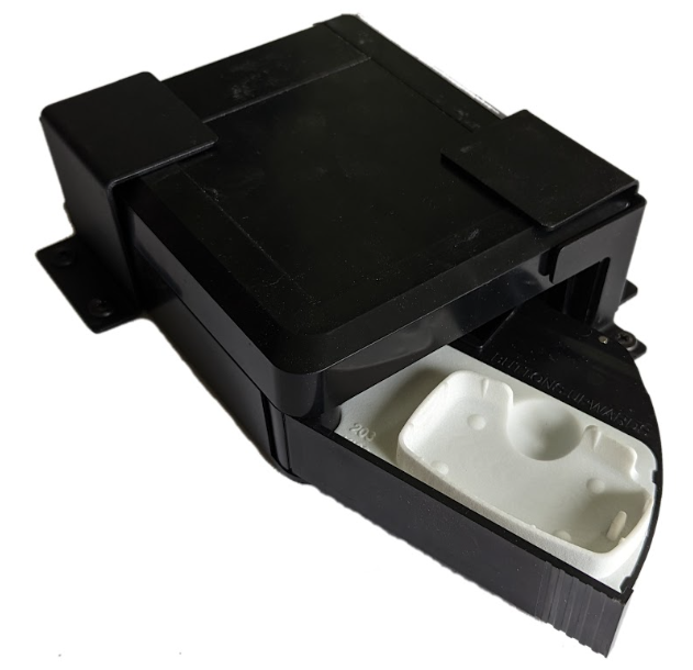
IOX-KEYBOX
Support Document
0 mins to read
The IOX-KEYBOX allows remote access to a vehicle without requiring an embedded key or digital OEM support. The device supports multiple markets including corporate car sharing, consumer car sharing, and traditional car rental services.
For the most up-to-date version of this document, visit: https://gtb.page.link/RywD
The IOX-KEYBOX enables shared vehicle access and works seamlessly with Geotab’s Keyless Platform. The device supports multiple markets including car sharing, car rental, shared vehicle pools, and shared vehicle access for delivery and field service vehicles, among others.
Features
- Easy to install in any vehicle without permanent modifications.
- Allows the vehicle fob to be integrated without damage.
- Allows for flexible use cases depending on the customer.
IOX hardware technical specifications
Physical
Dimensions | 164 x 139 x 61 mm |
Weight | 0.6 kg (Excludes key fob weight) |
Key fob Compatibility | |
Temperature Range | -30℃ to +60℃ (key fob dependent for ranges from -15 ℃ to -30 ℃) |
Protection Class | IP31 |
Electrical
Voltage Range | 9 V - 16 V (24 V not supported) |
Current | Low power sleep: < 2.5 mA (120 ms BLE scan every 3 s) Active key fob presses: <= 3 A (peak motor actuation) |
Bluetooth Module | BLE 5.1 |
Interfaces | CAN 2.0 A/B, CAN FD |
Connectors | Male Mini-USB Type-B connector: Daisy chain power and CAN in Female Mini-USB Type-B connector: Daisy chain power and CAN out Female C5 OBD connector: Accepts Geotab GO devices |
Harness Length | 3 m |
Certifications
Compliance: CE, FCC, ISED, RoHS, REACH, WEEE, UKCA, E-Mark
Availability
North America
- Canada
- United States of America
Europe (Schengen Area)
- Austria
- Belgium
- Czech Republic
- Croatia
- Denmark
- Estonia
- Finland
- France
- Germany
- Greece
- Hungary
- Iceland
- Italy
- Latvia
- Liechtenstein
- Lithuania
- Luxembourg
- Malta
- Netherlands
- Norway
- Poland
- Portugal
- Slovakia
- Slovenia
- Spain
- Sweden
- Switzerland
British Isles
- Great Britain
- Ireland
Installation
A GO9 or later device is required for operation of the IOX-KEYBOX. For GO9 device installation and setup, refer to the Telematics Device Quick Start Guide, and the HRN-GS16K22 T-Harness guide.
Before installing the IOX-KEYBOX, do the following to ensure the key fob is compatible:
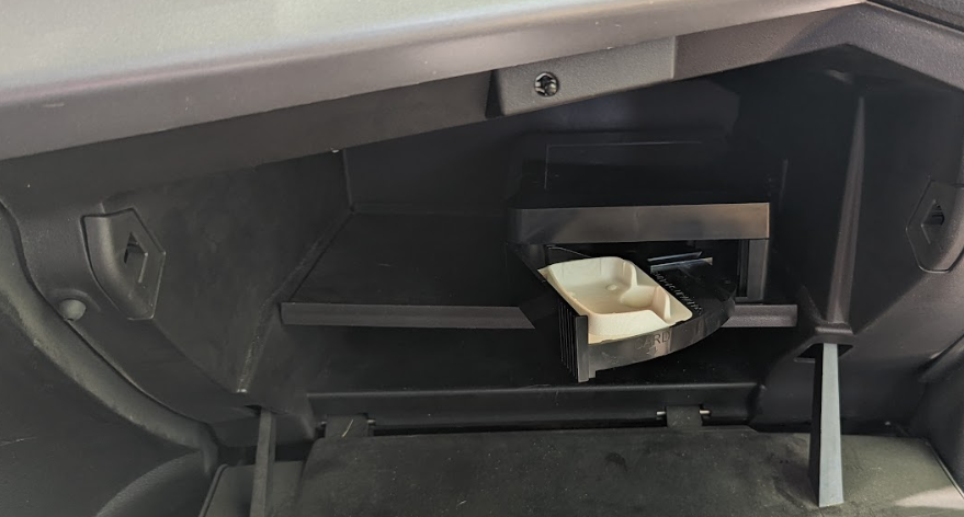
- Check that the 3 digit KEYBOX type code found inside the drawer on the white key tray matches the key fob photo found in the KEYBOX catalog.
- Physically place the key fob in the white tray and ensure a snug and secure fit, such that the fob easily snaps in place.
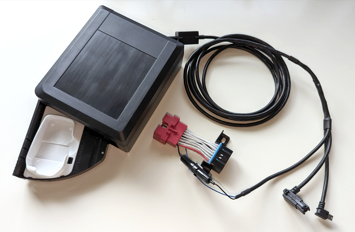
Kit contents
The IOX-KEYBOX container includes the following:
- IOX-KEYBOX unit
- HRN-KEYBOX cable (3.5 meters)
- Three Velcro fasteners
- Mounting brackets*
- Optional Key Power Control (KPC)
* Product will be available at a later date.
Inspect the units for any damage prior to installation. If there is damage or a strong odor, contact Geotab Support at +1 800 397-7102 for assistance.
Key Power Control (KPC) installation (optional for bladed fobs)
The Key Power Control (KPC) unit is necessary for use on all push-to-start vehicle installations. The KPC unit is optional. The KPC replaces the key fob battery with power from the IOX-KEYBOX, where it is only powered when required. This accessory aids in preventing the vehicle from being operated without authorization.
KPC polarity:
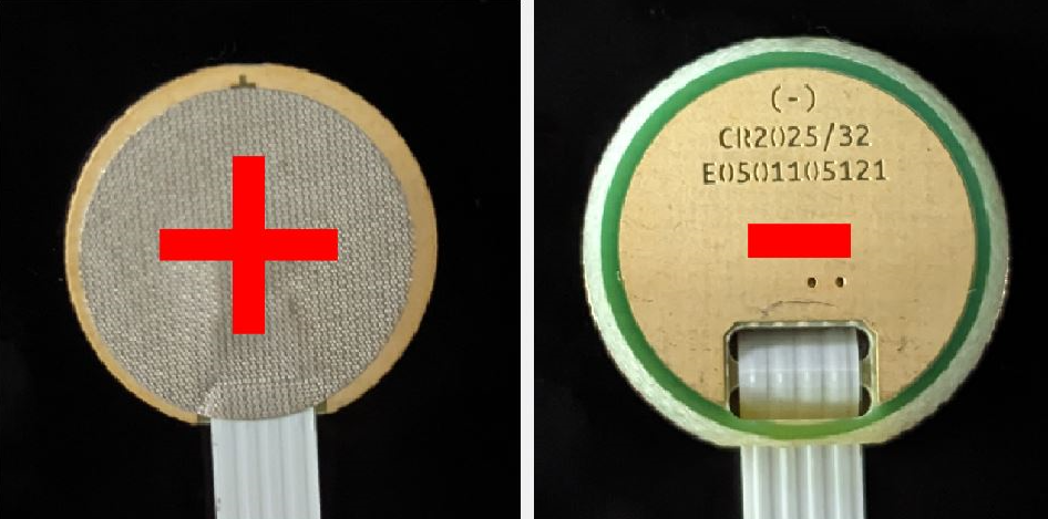
1 | Open the key fob, in accordance with the manufacturer's instructions. | 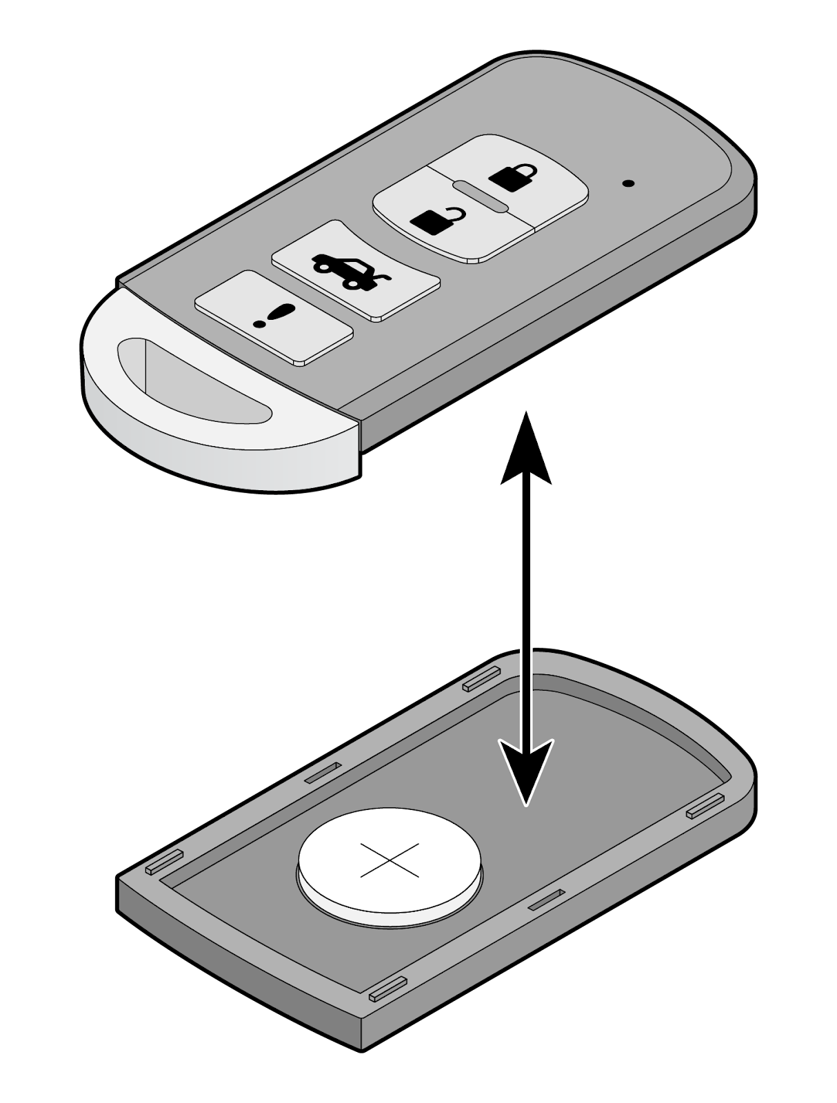 |
2 | Remove the manufacturer's battery from the key fob. | 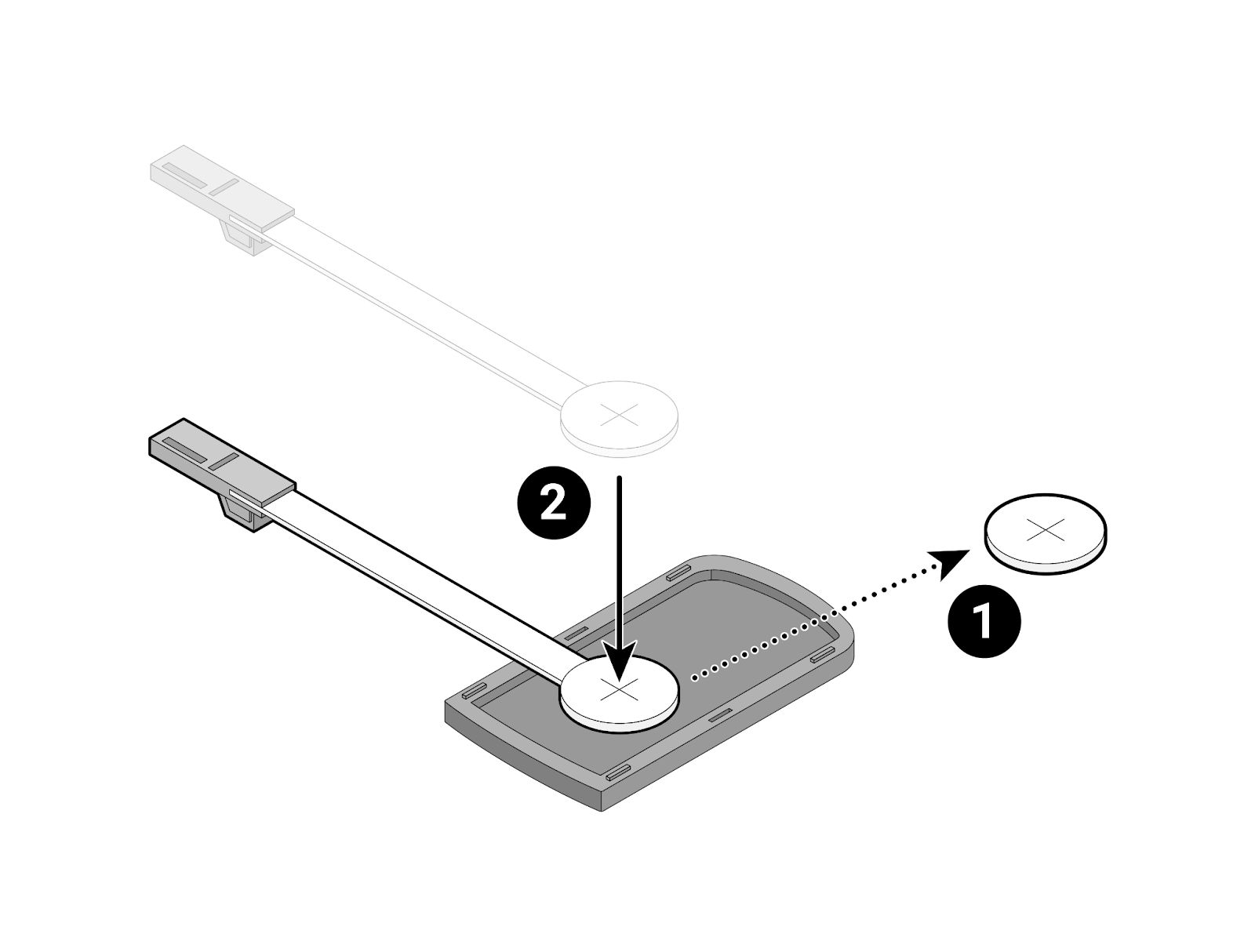 |
3 | Place the corresponding KPC in the battery position. Ensure the cable will exit the keyfob and pass under the keyfob to the power socket. | 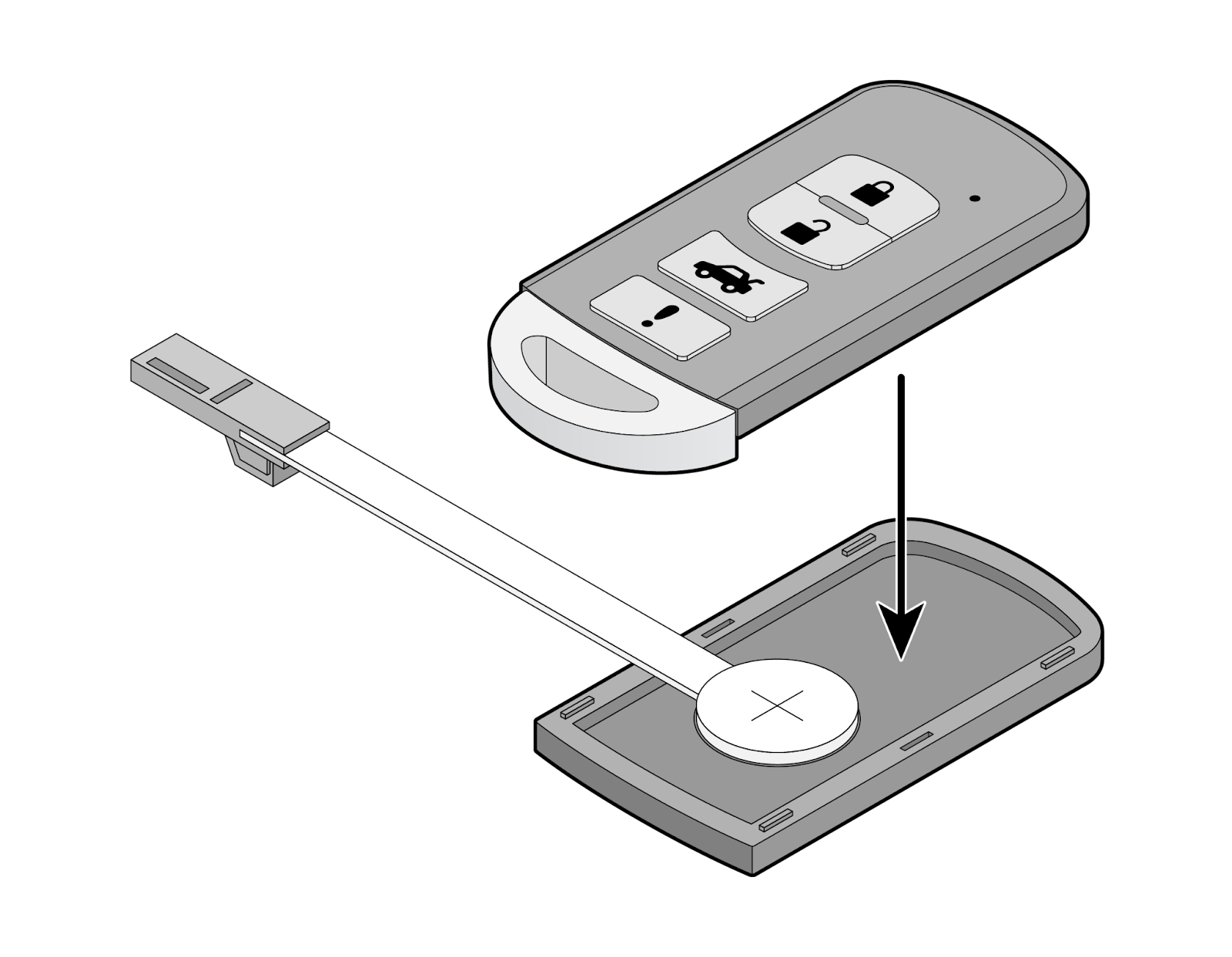 |
4 | Close the key fob with the upper part and bend the cable in the direction, as seen in the image. Pre-bending of the cable may be required to avoid cable damage. Ensure it is not stretched and contours the fob to minimize strain. | 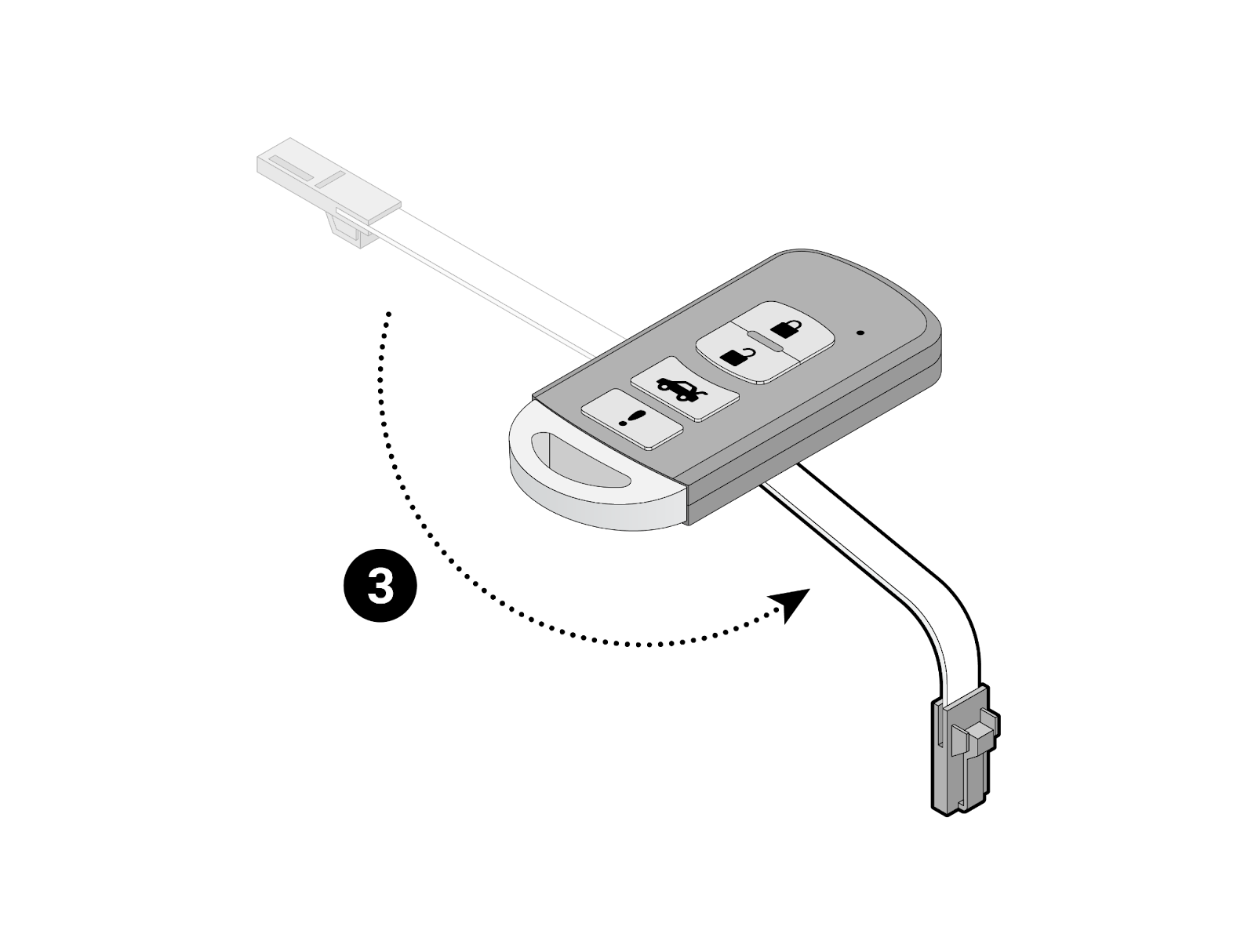 |
5 | Connect the plug to the socket in the key bed of the box drawer. Ensure the cable exits and passes under the keyfob to the power socket. This prevents excessive cable from interfering with the IOX-KEYBOX operation. | 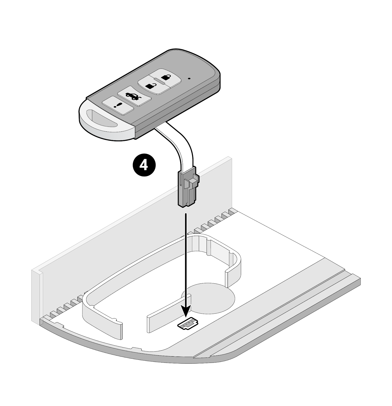 |
6 | Place the key fob in the key bed. | 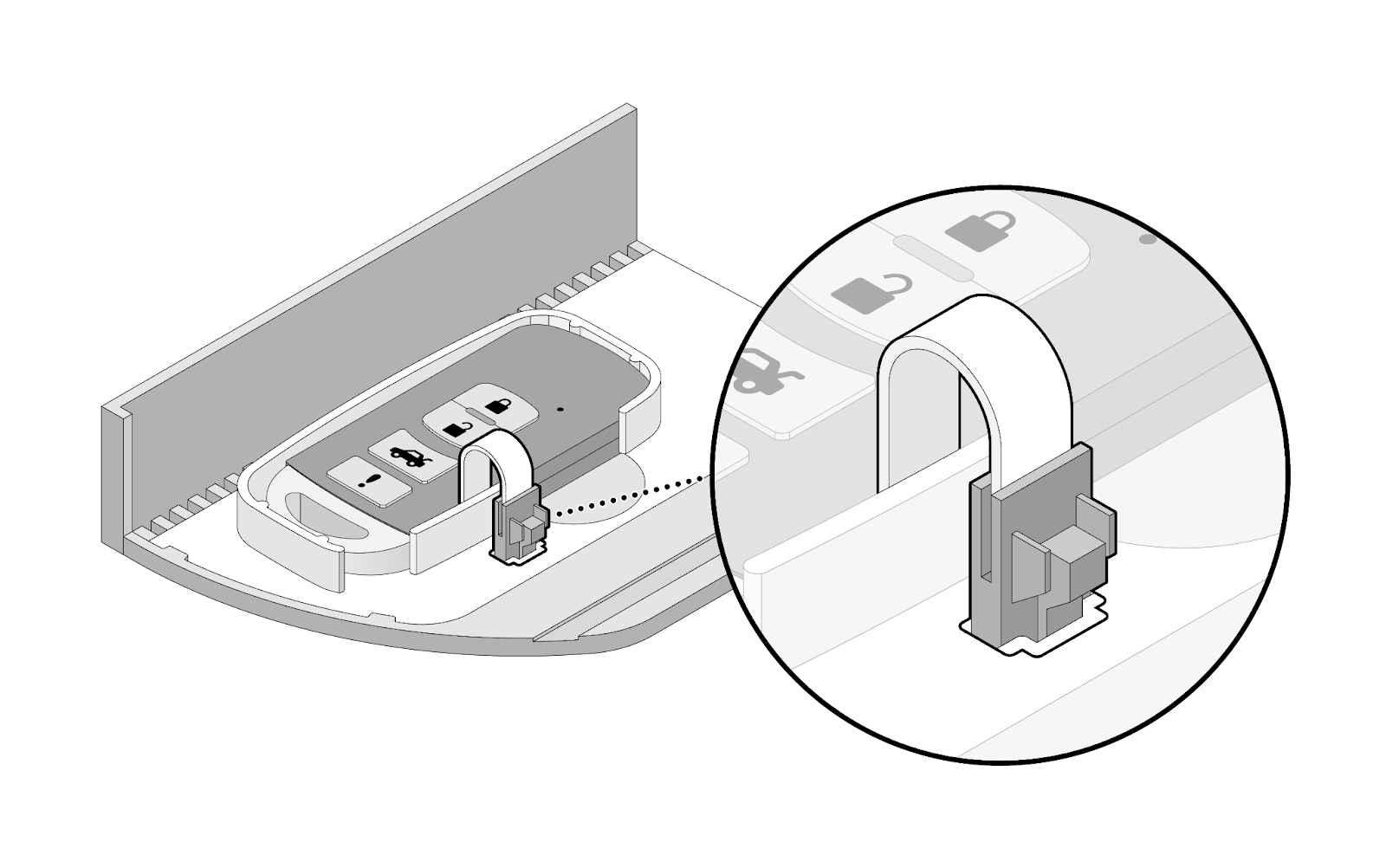 |
7 | Carefully close the drawer of the box, ensuring not to damage any cables. |
Guidelines for mounting locations
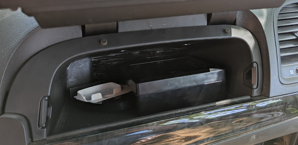
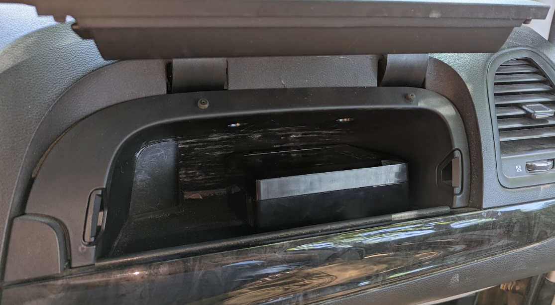
! IMPORTANT: To ensure the key fob remains in place and the unlock/lock commands function reliably, the IOX-KEYBOX should be mounted horizontally. When mounting inside the glove compartment, where the glove compartment floor may tilt when opened or closed, mounting so the given angle is 45 degree or less from horizontal through its travel is acceptable. ! IMPORTANT: if the glove compartment door needs to be or will ever be slammed to shut, glove compartment mounting is not recommended.
The IOX-KEYBOX can be installed in a number of locations in the vehicle, depending on its size, configuration, and type. If no modifications can be done to the vehicle, we recommend installing the IOX-KEYBOX in one of the following locations:
- Inside the glove compartment
- Underneath the seat
The following alternative mounting locations require additional mounting brackets:
- In the cargo area.
- Under the rear vehicle seats.
- Inside the passenger footwell.
! IMPORTANT: Any additional IOX devices must be installed AFTER the IOX-KEYBOX, and only if the overall daisy chain will not exceed 3.5m.
WARNING! If the IOX-KEYBOX is installed inside the cabin area/cargo area of a vehicle, it must be contained or otherwise secured to the vehicle to prevent it from becoming a projectile in the event of a collision. Failure to properly secure the IOX-KEYBOX using the recommended brackets could result in serious personal injury and/or vehicle damage.
IOX-KEYBOX is NOT to be installed in the following locations:
- Where it is exposed to heating sources.
- Where it is exposed to water (IOX-KEYBOX is rated IP31).
- Where it is visible from outside the vehicle.
- Where it can interfere with the safe operation of the vehicle.
- Where it is not contained within, or physically mounted, or secured to the vehicle.
Installation instructions
The Installation Technician must consider the mounting locations of the IOX-KEYBOX and cable routing. Evaluate the safety of the installation, and determine an appropriate method to secure the IOX-KEYBOX.
NOTE! The functionality of the key fob in the installation location should be tested prior to mounting and installation.
IOX-KEYBOX — Glove compartment installation
Prior to installing any equipment, determine a suitable installation location based on the vehicle.
- Ensure the IOX-KEYBOX has adequate clearance for the tray to fully open.
- Consider how the HRN-KEYBOX cable will exit the location and route to the GO device. Avoid high angle bends that may pinch or damage the cable.
- Determine whether drilling may be required to provide suitable cable routing in glove boxes that are completely enclosed.
 |  |
 |  |
1 | Prepare the IOX-KEYBOX for installation, and attach the provided dual lock adhesive tape to the bottom of the IOX-KEYBOX. 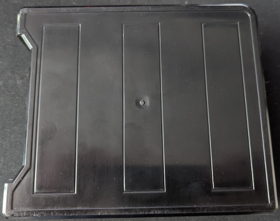 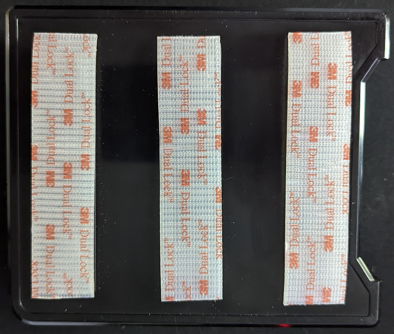 | |
2 | Route the HRN-KEYBOX cable from the IOX-KEYBOX through the access or drilled hole to the location of where the GO device will be installed. Ensure cable routing will not be a safety concern and is concealed within the dash. Secure the cable using cable ties. | |
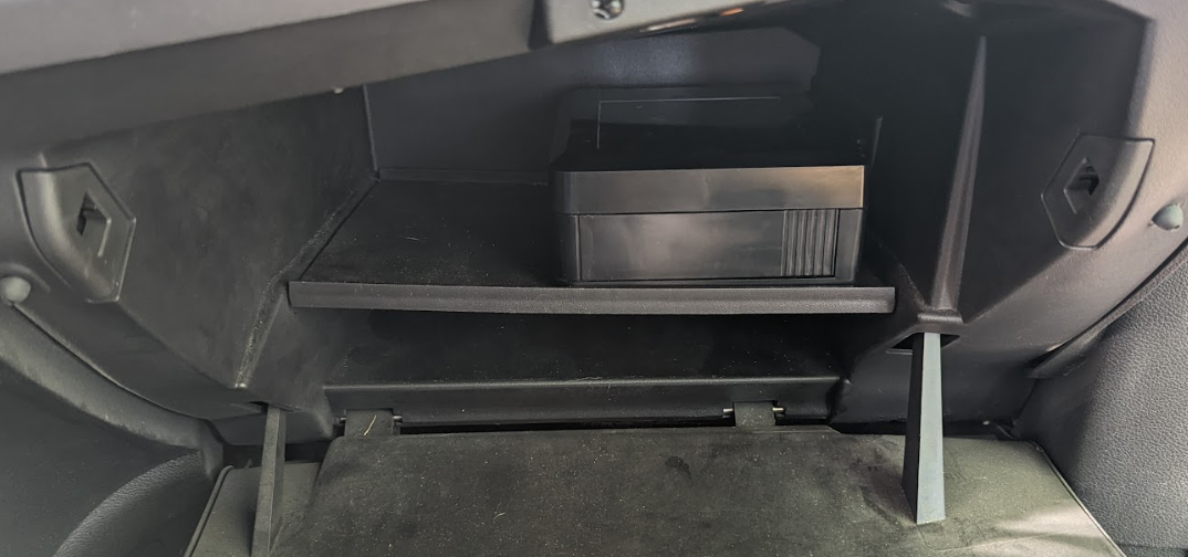
3 | Using the dual lock, mount the IOX-KEYBOX in the selected location. Ensure the IOX-KEYBOX is mounted securely, and the tray can fully open without obstruction. | |
4 | Attach the HRN-KEYBOX cable between the T-Harness and GO device, and the IOX connector to the GO IOX port. | |
5 | Install the T-Harness and GO device to the vehicle following instructions in the Telematics Device Quick Start Guide, HRN-GS16K22 T-Harness guide, and the Installation Video for GO9 with HRN-GS16K22. Ensure all cables and connections are secured with cable ties. NOTE! Ensure all IOX cables are connected to the GO device prior to connecting the T-Harness to the vehicle. ! IMPORTANT: Installers must perform the MyInstall Test (Steps 1-3B) - Telematics Device Quick Start Guide, (www.installmygps.com) while the vehicle is running. When logging the installation, ensure you see the IOX-KEYBOX listed under the Connected equipment section. If needed, follow the steps in the troubleshooting section.
 |
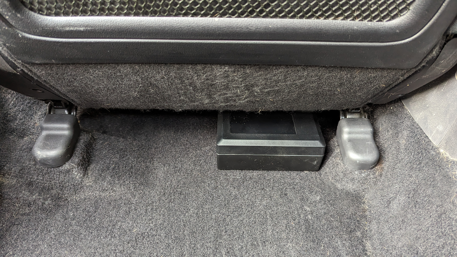
IOX-KEYBOX — Under seat or cargo area installation
Prior to installing any equipment, determine a suitable installation location based on the vehicle.
- Ensure the IOX-KEYBOX has suitable clearance for the tray to fully open.
- Consider how the HRN-KEYBOX cable will exit the location and route to the GO device. Avoid high angle bends that may pinch or damage the cable.
- Ensure there is clearance to properly install the mounting brackets.
- Mount the IOX-KEYBOX horizontally (flat) and fasten to the vehicle structure.
✱ NOTE: When installing in the cargo or under the rear passenger seat areas, additional attachment brackets are required to secure the device.
1 | Select a suitable mounting location that satisfies the mounting requirements for the IOX-KEYBOX. | |
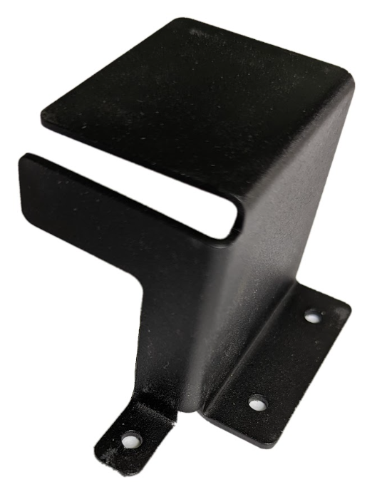
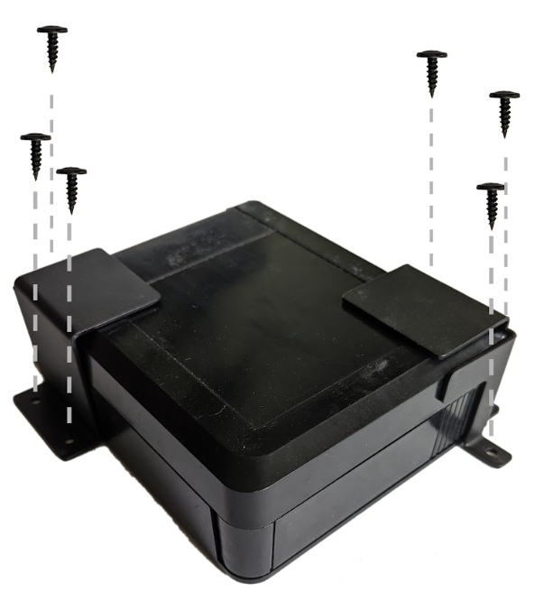
2 | Use the two mounting brackets — must be ordered separately — to securely mount the IOX-KEYBOX under the seat or in the trunk or cargo area. The brackets install diagonally to each other at the corners of the IOX-KEYBOX and secured with the supplied screws. Ensure the door functions and the brackets restrain the IOX-KEYBOX from movement or removal.
   | |
✱ NOTE: When mounting under the passenger seat, ensure you are not directly in front of the hot air duct or heat source. Example shown:
 | ||
3 | Route the HRN-KEYBOX cable from the IOX-KEYBOX to the location of where the GO device will be installed. Attach the HRN-KEYBOX cable between the T-Harness and GO device, and the IOX connector to the GO IOX port. | |
4 | Install the T-Harness and GO device to the vehicle following instructions in the Telematics Device Quick Start Guide, HRN-GS16K22 T-Harness guide, and the Installation Video for GO9 with HRN-GS16K22. Ensure all cables and connections are secured with cable ties. NOTE! Ensure all IOX cables are connected to the GO device prior to connecting the T-Harness to the vehicle. | |
5 | ! IMPORTANT: Installers must perform the MyInstall Test (Steps 1-3B) - Telematics Device Quick Start Guide, (www.installmygps.com) while the vehicle is running. When logging the installation, ensure you see the IOX-KEYBOX listed under the Connected equipment section. If needed, follow the steps in the troubleshooting section.
 | |
Example of final installation:
Termination Shunt
The IOX comes with a termination shunt installed in the expansion port. If you plan to install more than one IOX in a daisy chain, you must remove the shunt from each device in the line, except for the last IOX connected. The shunt must remain in the last IOX and secured with a zip tie.
The shunt in the last IOX device ensures the GO device detects and configures the IOX as effectively as possible.
✱ NOTE: Failure to install the shunt in the last IOX may affect IOX communication. To ensure the IOX communicates, please secure the shunt with a zip tie.
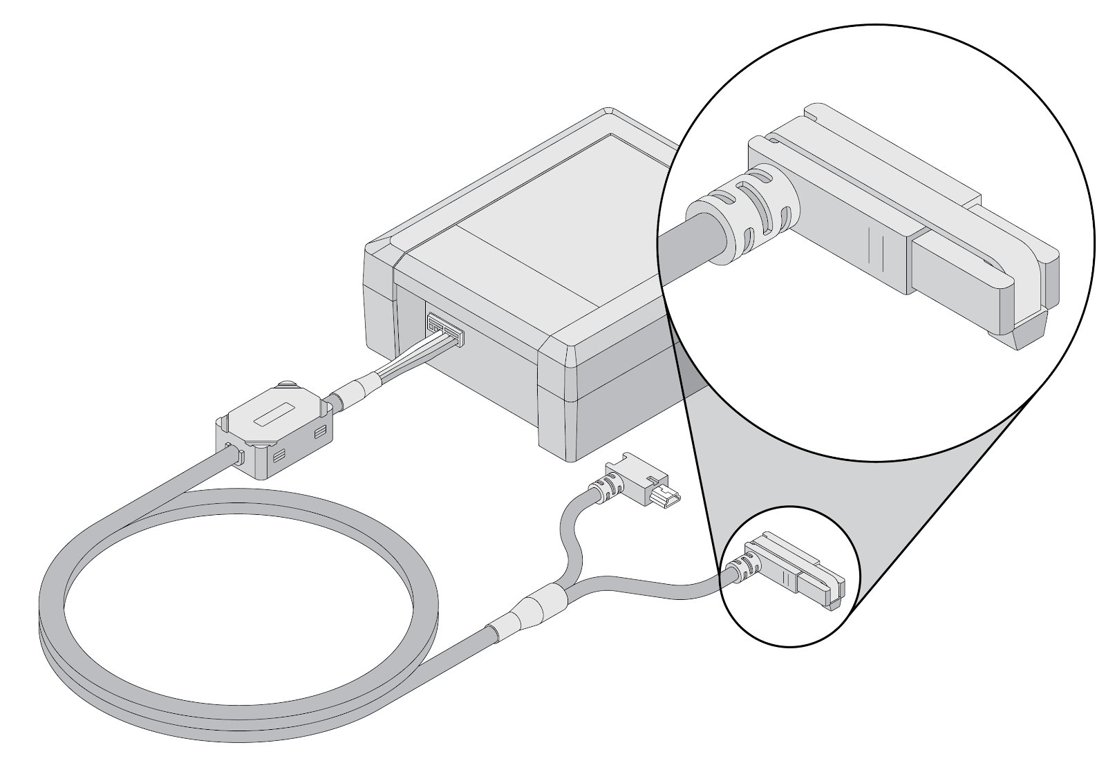 Figure 1: Termination shunt installed | 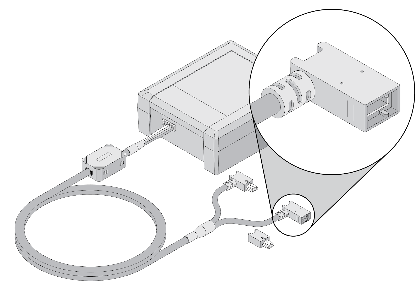 Figure 2: Termination shunt not installed |
Important Safety Information and Limitations of Use
For the latest version of Limitations of Use, please visit: goo.gl/k6Fp0w.
WARNING! Do not attempt to install, configure or remove any product from any vehicle while the vehicle is in motion or otherwise in operation. All installation, configuration or removal must be done only in stationary vehicles which are securely parked. Attempting to service units while being operated could result in malfunctions or accidents, leading to death or serious personal injury.
WARNING! All in-vehicle devices and related cabling must be securely fastened and kept clear of all vehicle controls, including accelerator, brake and clutch pedals. You must inspect devices and cabling on a regular basis to ensure all devices and cabling continue to be securely attached. Loose cabling or devices may impede the use of vehicle controls, resulting in unanticipated acceleration, braking or other loss of vehicle control, which could lead to death or serious personal injury. Improperly fastened in-vehicle devices may detach and impact operators upon sudden acceleration or deceleration, which may cause injury.
WARNING! If at any point after an in-vehicle device is installed a warning light illuminates on the vehicle dash or the vehicle stalls or has a marked drop in performance, shut off the engine, remove the device, and contact your Reseller. Continuing to operate a vehicle with these symptoms can cause loss of vehicle control, and serious injury.
WARNING! Your in-vehicle devices must be kept clear of debris, water and other environmental contaminants. Failure to do so may result in units malfunctioning or short-circuiting that can lead to a fire hazard or vehicle damage or serious injury.
WARNING! Do not attempt to remove the devices from the vehicle in which they are originally installed for installation in another vehicle. Not all vehicles share compatibility, and doing so may result in unexpected interactions with your vehicle, including sudden loss of power or shutdown of the vehicle’s engine while in operation or cause your vehicle to operate poorly or erratically and cause death or serious injury and/or vehicle damage.
NOTICE — This product does not contain any user-serviceable parts. Configuration, servicing, and repairs must only be made by an authorized reseller or installer. Unauthorized servicing of these products will void your product warranty.
Regulatory Statements
Warning: RF Exposure Compliance
The antenna(s) used for this transmitter must be installed to provide a separation distance of at least 20 cm from all persons and must not be co-located or operating in conjunction with any other antenna or transmitter. Users and installers must be provided with antenna installation instruction and transmitter operating conditions for satisfying RF exposure compliance.
L'antenne ou les antennes utilisées pour cet émetteur doivent être installées pour fournir une distance de séparation d'au moins 20 cm de toutes les personnes et ne doivent pas être co-localisées ou fonctionner en conjonction avec une autre antenne ou émetteur. Les utilisateurs et les installateurs doivent recevoir des instructions d'installation de l'antenne et les conditions de fonctionnement de l'émetteur pour satisfaire la conformité à l'exposition aux RF.
Canada
CAN ICES-003 (B) / NMB-003 (B)
This device contains licence-exempt transmitter(s)/receiver(s) that comply with Innovation, Science and Economic Development Canada’s licence-exempt RSS(s). Operation is subject to the following two conditions:
- This device may not cause interference.
- This device must accept any interference, including interference that may cause undesired operation of the device.
L’émetteur/récepteur exempt de licence contenu dans le présent appareil est conforme aux CNR d’Innovation, Sciences et Développement économique Canada applicables aux appareils radio exempts de licence. L’exploitation est autorisée aux deux conditions suivantes :
- L’appareil ne doit pas produire de brouillage;
- L’appareil doit accepter tout brouillage radioélectrique subi, même si le brouillage est susceptible d’en compromettre le fonctionnement.
USA
This device complies with part 15 of the FCC Rules. Operation is subject to the following two conditions: (1) This device may not cause harmful interference, and (2) this device must accept any interference received, including interference that may cause undesired operation.
✱ NOTE: This equipment has been tested and found to comply with the limits for a Class B digital device, pursuant to part 15 of the FCC Rules. These limits are designed to provide reasonable protection against harmful interference in a residential installation. This equipment generates, uses and can radiate radio frequency energy and, if not installed and used in accordance with the instructions, may cause harmful interference to radio communications. However, there is no guarantee that interference will not occur in a particular installation. If this equipment does cause harmful interference to radio or television reception, which can be determined by turning the equipment off and on, the user is encouraged to try to correct the interference by one or more of the following measures:
- Reorient or relocate the receiving antenna.
- Increase the separation between the equipment and receiver.
- Connect the equipment into an outlet on a circuit different from that to which the receiver is connected.
- Consult the dealer or an experienced radio/TV technician for help.
Changes or modifications not expressly approved by Geotab could void the user’s authority to operate the equipment.
EU
Product Wireless Information: 13.56 MHz: Max -6.52 dBuA/m H-Field strength 2400-2483.5 MHz: Max 0.3 dBm EIRP
SCIP Number(s) 53dfd948-a4a3-4a14-b000-317c1f8f7e91 0b83ba52-1252-4266-b0d7-1814bc08fd76
Germany
Wir besitzen keine Versand- und Lagerfläche in Deutschland und sind nicht von der Rücknahmepflicht nach § 17 ElektroG betroffen.
IOX-KEYBOX is manufactured by WITTE:digital, A Business Unit of WITTE Automotive GmbH, Hoeferstr. 3-15, D-42551 Velbert, Germany