GO Device Installation for Rail Service Vehicles
Installation Guide
0 mins to read
Learn how to connect a GO device to Rail Service vehicles (including Hi-Rail). Includes images of the kit contents, procedures for installing the GO device, and how to contact Support to check the installation.
July 2024Table of contents
Kit contents
The GO device kit for rail service vehicles includes the following:
|
|
Either one of the following:
✱ NOTE: Some Heavy-Duty vehicles require a vehicle-specific FMS harness. |
|
(Optional) IOX-AUXM harness: |
|
(Optional) Hi-rail magnetic sensor (part number 03-01-0005 or 03-69-0116): For more information, see the Hi-rail wiring section of this document. |
|


Preparing for installation
Before installing the GO device, complete the following prerequisites:
- Inspect the vehicle
- Determine the best location to install the GO device, taking Customer needs into consideration
- Receive Customer sign-off regarding the installation plan.
Recommended tools and supplies
In addition, we recommend you have the following tools and supplies ready before installing the GO device:
- Drill with extra battery
- Sharp metal drill bits (for ¼” (7mm) hardened steel)
- Either wire and loom or exterior heavy jacket cable (weather-resistant)
- Various fastening hardware stainless steel (Nuts, bolts, and lock washers) to mount sensor bracket to hi-rail system
- Stainless steel self-tapping screws (optional)
- Bolt cutters
- Cable ties
- Voltmeter and ohmmeter
- Pry tool for removing trim panels
- Solder, supplies solder iron or mini torch, and heat shrink to extend wires to IOX-AUXM
- PPE (safety glasses, steel toe shoes, reflective vest, hard hat, etc.)
Installing the GO device
Recording vehicle and device information
Record the following information before proceeding with the installation. This information will be needed later during the install check.
- Serial number of the GO device (pictured below)
- Vehicle fleet number or license plate
- Vehicle year/make/model and VIN
- Odometer and engine hours (if available)

Finding a suitable mounting location
Locate an unexposed and dry place to mount the GO device. This is typically found under the dash.
The device must be mounted to a solid part of the vehicle, either on the chassis (frame) or on any other solid surface that will not move or vibrate excessively during normal use of the vehicle.
! IMPORTANT: Ensure that the GPS antenna is facing skyward. For GO7 and all subsequent devices, the GPS antenna is located at the “bottom” of the device:
Telemetry interfacing and wiring for IOX-AUXM (Optional)
Install and interface the GO device to telemetry sensors as required.
! IMPORTANT:
- The IOX-AUXM must be plugged into the GO device or the IOX chain before powering the GO device. This ensures that the IOX is recognized.
- For about 30 minutes after powering on the GO device for the first time (all three LEDs flash and six swift beeps sound), the device enters debug mode, and any attached IOX-AUXMs enter input learning mode.
- For consistent learning results, have all telemetry inactive or off before powering the GO device. Then, start the vehicle engine, and once all three LEDs are on, cycle through all applicable telemetry for 15 seconds. For example, turn on PTO for 15 seconds and then turn it off, move the hi-rail down for 15 seconds and then back up, and so on.
- While in learning mode, the GO device beeps X times for each change in state where X is the AUX number. For example, if the hi-rail is wired to AUX2, the device will beep twice when the hi-rail is lowered or raised. Use this to verify that the connections are working properly.
- One IOX-AUXM supports up to four auxiliary inputs. If additional inputs are required, see Expanding the IOX-AUXM.
! IMPORTANT: Make note of which telemetry sensors you connect, because this information will be needed later during the install check.
Wire | Telemetry | Wire color | Loop (red & black) | Active (input level) | Inactive (output level) |
AUX1 | Power take-off (PTO) | Blue | Short | On (power) | Off (float) |
AUX2 | Hi-rail | Orange | Short | Down (ground) | Up (float) |
AUX3 | Crane | Green | Short | Up (ground) | Down (float) |
AUX4 | Compressor | White | Short | On (ground) | Off (float) |
AUX5 | Generator | Blue | Cut loop | On (power) | Off (float) |
AUX6 | Welder | Orange | Cut loop | On (ground) | Off (float) |
AUX7 | Tool circuit | Green | Cut loop | On (power) | Off (float) |
AUX8 | Panic | White | Cut loop | On (power) | Off (float) |
Expanding the IOX-AUXM
While each IOX-AUXM only reports four auxiliary inputs, you can daisy-chain two IOX-AUXMs together to report up to eight auxiliary inputs. By default, an IOX-AUXM will report AUX 1 through 4. To make an IOX-AUXM report AUX 5 through 8, cut the red and black loop covered in heat shrink, known as the short. |
| |
✱ NOTES:
| ||

Termination shunt
The IOX-AUXM comes with a termination shunt installed in the expansion port. If you are installing more than one IOX in a daisy chain, you need to remove the shunt from each device in line except the last IOX. That shunt must remain installed and be secured with a zip tie. |
Hi-rail wiring
This section describes how to wire hi-rail sensors to the GO device in hi-rail vehicles.
There are two different versions of sensors: magnetic sensors and proximity sensors. Refer to Wiring Schematics for instructions on how to mount and wire the proximity sensor.
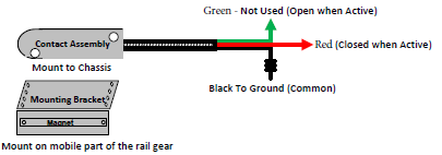
The following applies to mounting magnetic sensors. Both types of magnetic sensors have a contact assembly (magnetic switch) and a mounting bracket (magnet).

Connect the red sensor wire to the orange (AUX2) input on the IOX-AUXM cable.


Wiring schematics
Sensor model 03-01-0005 (Manufacturer: George Risk Industries, part number 4402-A):


Sensor model 03-69-0116:

✱ NOTES:
- There must be a negative signal (ground equivalent) when the hi-rail is down and no connection (open circuit) when the hi-rail is up or locked.
- When the hi-rail is up (that is, the vehicle is on the road), the sensor and magnet should be within 0.5” to 1.5” of each other.
- When the hi-rail is down (the vehicle is on rails), the sensor and magnet move away from each other, causing the sensor to send a ground signal on the red sensor wire connected to the orange (AUX2) input on the IOX-AUXM cable.
- For both sensor models, the second wire should be run to the inside of the cab, to connect the magnetic sensor wire (white wire on model 03-01-0005, black wire on model 03-69-0116) to a reliable vehicle ground point near the location where the red sensor wire connects to the orange (AUX2) input on the IOX-AUXM cable.
- It is not recommended to ground the wires to the outside frame of the vehicle to avoid corrosion or damage that may result from debris or extreme weather conditions.
Proximity Sensor
! IMPORTANT: The Proximity Sensor instructions apply to Hi-Rail solutions manufactured by Harsco Industries, for projects where they supply the proximity sensor and 5m cable.
To mount the proximity sensor:
- Use the provided proximity sensor (ifm efector inc. part number: IGM206-00 w/5m cable) and mount within the pre-drilled hole. Mount so the LED on the proximity sensor shaft points towards the front of the vehicle.
- Use a feeler gauge to ensure a 5mm (3/16”) gap between the end of the sensor and the hi-rail cam. (See red lines in the photo below.
- Lock the 18mm nuts in place using ~ 40nM (30 ft-lb) of torque.
- Run the harness into the under dash area near the vehicle’s OBD connector (where the GO device will be installed). Cover the harness with split wire loom or braided sleeving for the exterior run to protect it from flying debris and secure it every 15 to 30 cm (6 to 12 inches) in locations where it will not become pinched or damaged using cable ties.

Wiring schematics
Sensor model, ifm efector inc. part number: IGM206-00 w/5m cable Color code: BN = BrownBK = BlackBU = Blue |
|

To connect the sensor wires:
- Connect the sensor’s brown wire to the vehicle ignition and fuse with a 5 amp fuse. The vehicle ignition point should be a 15 A fuse or higher.
- Connect the sensor’s blue wire to a reliable vehicle ground.
- Connect the sensor’s black wire to IOX-AUXM’s orange wire (AUX2).
- Local tests; with the ignition on, cycle the Hi-Rail and ensure the proximity sensor’s LED cycles on/off to coincide with Hi-Rail engaged and stowed positions.
Once you have connected the sensor, you must call support to test the connection and ask support to invert the AUX2 signal.
Inverting the AUX2 Signal
Once the sensor is connected, the AUX2 signal must be inverted. This can be done in MyGeotab.
- Select the appropriate asset from the Vehicles & Assets page.
- Select the Settings tab at the top of the asset’s page.
- Under Aux 2, toggle Invert input value to On. The toggle is in the On position when it is highlighted in blue.
- Click Save at the top of the page to save your changes.

Power take-off (PTO) wiring
The power take-off connects to the AUX1 wire on the IOX cable.
When the PTO is engaged, there must be a negative or positive signal.
When the PTO is disengaged, the signal must be the opposite of the above (or float).
The mechanical gearbox is mounted on the transmission, but in most cases, a PTO switch or relay circuit inside the cab can be used instead.
Performing an install check
Once you have installed all elements required by the Customer, you need to perform an install check. This can be done by calling our support team at 1-888-776-3333, Monday to Friday, 8 a.m. to 5 p.m. EST.
Be sure to have all the following information readily available:
- Serial number of the installed GO device
- Vehicle fleet number or license plate
- Vehicle year/make/model and VIN
- Odometer and engine hours (if available)
- A list of any telemetry connections that were made (if applicable)
