GO9 RUGGED Support Document
Support Document
0 mins to read
Learn more about the GO9 RUGGED, a ruggedized telematics device that offers GPS technology, g-force monitoring, Geotab IOX expandability, engine and battery health assessments, and the ability to communicate on the LTE network. The GO9 RUGGED is ideal for heavy equipment, yellow iron, agricultural machinery, and oil field equipment.
Geotab® GO9 RUGGED™ — Ruggedised telematics device
For the most up-to-date version of this document, please visit this link.
GO9 RUGGED device
Geotab’s GO9 RUGGED telematics device is the most powerful yet. The GO9 RUGGED offers a 32-bit processor, four times more memory and five times more RAM than the GO8 RUGGED®. Similar to the GO8 RUGGED, the GO9 RUGGED offers state-of-the-art GPS technology, G-force monitoring, GEOTAB IOX® expandability, engine and battery health assessments and communication on the LTE network*.
Vehicle tracking
Using Geotab’s patented tracking algorithm, the GO9 RUGGED accurately recreates vehicle trips and analyses incidents. The GO9 RUGGED also offers in-vehicle alerts to instantly notify drivers of infractions and—with hardware Add-Ons—provides live coaching for driver on-road performance. The GO9 RUGGED does not require a dash-mounted aerial or any wire splicing.
Security
Geotab platform security is designed for the end-to-end protection of your data.
Key implementations include:
- GO devices and network interfaces use authentication, encryption and message integrity verification.
- GO devices are individualised. Each device uses a unique ID and non-static security key, making it difficult to fake a device’s identity.
- Over-the-air updates use digitally signed firmware to verify that updates come from a trusted source.
- Geotab uses independent third-party experts to validate the platform from end to end.
- FIPS 140-2 validated firmware module used for performing cryptography (certificate #3371).
✱ NOTE: FIPS 140-3 Inside (Certificate #4875), deploying soon.
Top features
|
Technical specifications and features
Interfaces | Engine Management
Input/Output
|
Cellular | Availability varying on certification — full list of supported countries here. (GR9-LTE) GO9 RUGGED LTE ATT/TELUS/ROGERS, ATT and ROGERS with limited availability
(GR9-LTE) GO9 RUGGED LTE Verizon
(GR9-LTM) GO9 RUGGED LTE CATM1 Oceania
(GR9-LTM) GO9 RUGGED LTE CATM1 EMEA
(GR9-3G) GO9 RUGGED 3G/2G Global
3GPP Compliant |
GPS Receiver | 72-channel engine (GPS/GLONASS) Under 2 second Time-To-First Fix for hot and aided starts Cold start: 26s E1 and Above Models: Cold Start under 24s. Below E1: Cold start : under 26 s E1 and Above Models: Concurrent GPS, GLONASS, Galileo and BeiDou plus SBAS and QZSS. Below E1: Concurrent GPS and GLONASS plus SBAS and QZSS. Accuracy: ~2.0 m CEP OTA FW updates supported |
Environmental | Operating Temperature: −40 to +85 °C SAE J1455 Temperature
Humidity
Salt Spray (Fog) Mechanical Vibration
Mechanical Shock
General Heavy-Duty Truck Electrical Environment
IEC 60529 IP6X IPX8 IPX9K |
Accelerometer & Gyroscope | 3D accelerometer and 3D gyroscope. Full-scale acceleration range of ±8g and an angular rate range of ±250 dps. |
Mechanical | Weight: 396 g (0.87 lbs) Casing Dimensions: 159 mm L × 122 mm W × 31 mm H Cable Length: 1000 mm Housing: Polycarbonate (PC) thermoplastic two-piece housing (Flammability rating: UL 94 V-0) |
Electrical | Voltage: 12 V and 24 V systems supported ! IMPORTANT: Maximum battery voltage that can be supplied to the GO9 RUGGED device is 36V. Current
✱ NOTE: Maximum current draw values are reached during transmission in regions with fair to excellent cellular coverage. Maximum current draw at 24 V will be less than at 12 V. GO9 devices can pass through a maximum total current of 2750 mA @ 12 V/24 V to IOX hardware in a daisy chain via resettable overcurrent protection. ✱ NOTE: For each IOX in the daisy chain, add their max current draw, and do not exceed the max total IOX current draw. |
Compliance | FCC, ISED, PTCRB, NOM, CE, E-Mark, REACH, RoHS, WEEE, RCM, UKCA, RAMATEL, ANATEL, SUBTEL, CRC, Indotel, ARCOTEL, SDPPI, SIRIM, ANRT, TRA, MTC, IMDA, NBTC Carriers: AT&T, TELUS, Verizon, Telenor, Telefonica, Vodafone, Rogers, Bell, Telstra |
Over-the-Air (OTA) Support | Firmware Updates: For maintenance, new features, and custom applications Parameters: For turning additional features on/off Almanac/Ephemeris Data: For quicker GPS latch |
Voltage Recording | Curve-based voltage logging to detect weak batteries, failing alternators, and failing starters. |
64-Mb Non-volatile Flash Memory | Main Data Memory: Up to 80,000 logs in offline mode (out of coverage) Collision Data Memory: Buffer records over 100 minutes of second-by-second data (6,000 logs). Last 72 records (1.2 minutes) are sent instantly on accelerometer-triggered collision-level events. |
Recording Parameters | Patented curve-based GPS/voltage/accelerometer/engine data logging algorithm for fewer, more accurate data points. |
Intelligent Ignition | Non-engine-based ignition detection voltage and movement, allowing for 3-wire installation. Ideal for older vehicles with no engine information and covert installation for asset recovery. |
Differences between GO9 and GO9 RUGGED
Engine communication
The GO9 RUGGED does not support the following engine protocols and corresponding engine information:
- Single-wire CAN bus: Seat belt and odometer data on some GM, Fiat and Dodge vehicles.
- Medium-speed CAN bus: Ford transit and Mazda seat belt.
Buzzer and other IOX Add-Ons
The GO9 RUGGED is made for external environments and can be installed on the outside of a vehicle. The IOX-BUZZ (external buzzer) or IOX-GOTALK can be installed if driver feedback is required. The HRN-RX06S4 is required to connect any IOX to the GO9 RUGGED device.
Harness options
The GO9 RUGGED requires the following harnesses for successful vehicle and/or IOX installation. Please refer to the Harness Identification and Application document for more information on the best harness for your application. All harnesses in the table below are IP68-rated up to the boundary, as shown in Figure 1.
Harness Name | Description | Application Type |
12-way Amphenol weather-resistant rugged harness for GO RUGGED — PWR, GND, IGN. | 16-pin ALDL Connector | |
Universal rugged heavy-duty T-harness kit | 9-pin Deutsch Connector | |
CAT specific adapter for the GO RUGGED device (requires HRN-GR09K1) | 9-pin Deutsch Connector | |
3-wire harness kit for GO RUGGED. This kit contains the harness and a fuse kit. | No diagnostic connector available | |
6-way IOX harness for GO RUGGED to provide IOX add-on support. The gray connector is weather resistant. | IOX connection point for GO RUGGED | |
14-pin harness for CAT vehicles 2016+. | 14-pin Deutsch Connector | |
8-wire harness kit for GO RUGGED. This kit contains the harness and a fuse kit. | Customer OEM Diagnostic Connector | |
Differential harness used for negative battery disconnect, oil pressure switch, and/or negative output ignition for the GO RUGGED device. This is required for ground service equipment. The kit contains the harness and a fuse kit. Includes HRN-RW04S4. | Ground Service Equipment (GSE) | |
Kubota gas engine interface harness for the GO RUGGED device. This is required for ground service equipment. | Ground Service Equipment (GSE) | |
Ford EDI TUG engine interface harness for the GO RUGGED device. This is required for ground service equipment. | Ground Service Equipment (GSE) | |
Pulse harness for engines not reporting ignition/RPM for the GO RUGGED device. This is required for ground service equipment. | Ground Service Equipment (GSE) | |
12-pin Komatsu harness. | Construction, mining, forestry, and industrial equipment | |
HRN-RW07T1 | 3-pin Deutsch harness with J1939 HI, J1939 LO, and signal ground in the connector, with power and chassis ground as separate wires. This harness allows connection to the equipment's CAN bus without using the diagnostic connector, but still capturing the same engine data. | No harness matching the diagnostic connector available, or limited space |
HRN-RS12K1 | Battery disconnect bypass harness. | Any vehicle with a positive battery terminal disconnect kill switch |
Harness pin diagram and description for ALDL and IOX
For professional installation where specific cable routing is required, the terminals on the weather-resistant connectors can be de-pinned on both the GO9 RUGGED and the corresponding HRN-RS12S2 and HRN-RX06S4 harnesses. This allows the installer to route the wires through a smaller opening. The wires can then be re-pinned into the connectors as described in the tables below. In this way, the GO9 RUGGED can be installed in restricted spaces whilst maintaining its IP68 rating.
The GO9 RUGGED and its connectors are IP68-rated. The HRN-RX06S4 and HRN-RS12S2 are only IP67-rated in part and the grey connectors are the only weatherproof elements. Removal of the grey connectors on either the GO9 RUGGED or its harnesses will reduce the overall weatherproofing of the system. Figure 1 illustrates the scope of the weatherproofing for the GO9 RUGGED and its harnesses:
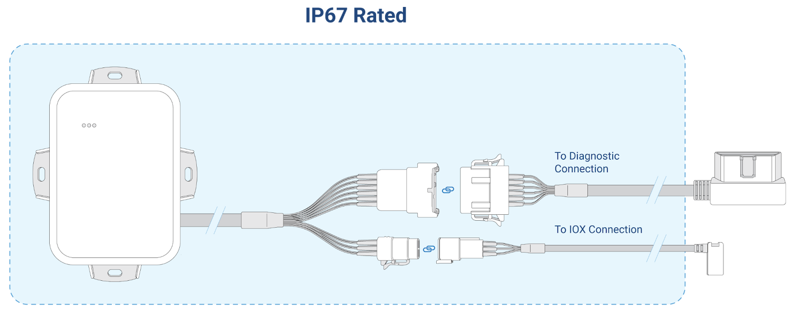
Figure 1: The blue region highlights the scope of the IP68 rating.
HRN-RS12S2/GO9 RUGGED — ALDL diagnostic port connector
✱NOTE: Not all pins are populated on all vehicles.
Pin | Wire colour | Description for ALDL port | Pin | Wire colour | Description for ALDL port |
1 | Orange | Ground (signal shield) | 7 | Brown | Make/model-specific |
2 | Green/white | CAN low/TTL CAN low | 8 | Pink | Make/model-specific |
3 | Blue/white | L line | 9 | Black | J1850 (+)/MODBUS |
4 | Brown/white | J1850 (-)/MODBUS | 10 | Green | K line |
5 | Purple/white | Make/model-specific | 11 | Yellow | CAN line/TTL CAN high |
6 | Grey | Make/model-specific | 12 | Orange/white | Power (12 V/24 V) |
HRN-RX06S4 — IOX port connector
Pin | Wire colour | Description for ALDL port | Pin | Wire colour | Description for ALDL port |
1 | Red | Power | 4 | Black | Ground |
2 | White | CAN low | 5 | Green | CAN high |
3 | Yellow | Wake up | 6 | — | — |
GO9 RUGGED — IOX port connector
Pin | Wire colour | Description for ALDL port | Pin | Wire colour | Description for ALDL port |
3 | Black/White | Power | 4 | White | Ground |
2 | Blue | CAN low | 5 | Purple | CAN high |
Preparing for installation
Before installing the GO device, please record the device serial number. The serial number is used to verify the communication status of the GO device.
Carefully read the device release notes (goo.gl/fZURff) or the vehicle-specific installation notes (goo.gl/MCIXt0) to verify that we support your vehicle. If you have any questions or concerns, please contact your reseller.
Ensure that no dashboard warning lights are on in the vehicle whilst it is running and that all other functions, such as headlights, indicators etc. are working prior to installing the device. Before installation, add the device to your MyGeotab database using the device serial number. This ensures that all data logged by the device is sent to your database.
✱ NOTE: You must select the correct Geotab hardware suitable for your specific installation environment and vehicle use. For installations where exposure to the elements (e.g. liquids, dust or interior wet cleaning/power washing) is anticipated, select the GO RUGGED device (GR8-rated IP67 and GR9-rated IP68 and IP69K). For additional information regarding environmental contaminants, see the applicable installation instructions in the Important safety information and limitations of use document.
Installation instructions
Professional installation required — Installation of the GO9 RUGGED requires that the installer has sufficient technical knowledge and expertise for mobile device installation and integration into modern vehicles, i.e. certified Geotab Installer certification or equivalent.
Read the important related safety information and limitations of use following these installation instructions. Read and follow all instructions and warnings to prevent serious injury and/or vehicle damage.
WARNING! Prior to GO installation, read and follow the important safety information including the limitations of use found after these installation instructions. Always read and follow all safety information to prevent loss of vehicle control and serious injury.
WARNING! Some installations are not straightforward and must be completed by an authorised Geotab Installer to ensure a secure installation. An unsecured device installation can cause poor electric and/or data connections that can lead to short circuits and fires or cause the malfunction of vehicle controls that can result in serious personal injury or significant damage to your vehicle. Some examples that require professional installation by an authorised Geotab Installer include:
- The OBD port location is such that the device protrudes and interferes with entering or exiting the vehicle or is located where it could be inadvertently kicked or bumped during vehicle operation
- The device isn’t fully secured and so may come loose from vibrations or accidental contact
- An electrical harness or additional wiring is required
- Vehicle mounting modifications are required to secure the device, i.e. removal of panels; deformed/damaged OBD connector or physical damage to the electrical wiring
- The device does not beep six times and power on when first installed
- The installer doubts their ability to complete a secure installation according to these instructions
WARNING! Do not attempt to install, reconfigure or remove any product from a vehicle whilst the vehicle is in motion or otherwise in operation. All installation, configuration or removal must be only carried out on stationary vehicles that are securely parked. Attempting to service devices whilst the vehicle is in motion could result in malfunction or collisions, leading to death or serious personal injury.
Please refer to the GO and GO RUGGED Device Installation FAQs if you have any questions during the installation process.
How to install the GO9 RUGGED device
For GO9 RUGGED installation instructions, refer to this page on the Geotab Installations site.
WARNING! All in-vehicle devices and related cabling must be securely fastened and kept clear of all vehicle controls, including the accelerator, brake and clutch pedals. This requires the use of a cable tie when securing the device or any extension harness to the OBD connector, securing both sides of the harness. If you do not use a cable tie, vibration in the vehicle can lead to a loose connection that could indirectly cause the vehicle’s engine computer to fail, a loss of vehicle control and cause serious injury. Inspect devices and cabling regularly to ensure that all devices and cables remain securely attached.
WARNING! If, at any point after an in-vehicle device is installed, a warning light appears on the vehicle dashboard or the vehicle stalls or has a marked drop in performance, turn off the engine, remove the device and contact your reseller. Continuing to operate a vehicle with these symptoms can cause loss of vehicle control and serious injury.
Important safety information and limitations of use
For the latest version of the limitations of use, please visit: https://gtb.link/k6Fp0w.
WARNING! Do not attempt to remove devices from the vehicle in which they are originally installed for installation in another vehicle. Not all vehicles share compatibility and doing so may result in unexpected interactions with your vehicle, including a sudden loss of power or the shut down of the vehicle’s engine whilst in operation. It may also cause your vehicle to operate poorly or erratically and cause serious injury and/or vehicle damage.
NOTICE: This product does not contain any user-serviceable parts. Configuration, servicing and repairs must only be made by an authorised reseller or installer. Unauthorised servicing of these products will void your product warranty.
NOTICE: The EU Declaration of Conformity is available at https://gtb.link/tf7m (3G) and https://gtb.link/EHcq (LTM).
Regulatory Statements
Warning: RF Exposure Compliance
The aerial(s) used for this transmitter must be installed providing a separation distance of at least 20 cm from all persons and must not be co-located or operating in conjunction with any other aerial or transmitter. Users and installers must be provided with aerial installation instructions and transmitter operating conditions for satisfying RF exposure compliance.
CANADA
CAN ICES-003(B) / NMB-003(B)
This device contains licence-exempt transmitter(s)/receiver(s) that comply with Innovation, Science and Economic Development Canada’s licence-exempt RSS(s). Operation is subject to the following two conditions:
- This device may not cause interference.
- This device must accept any interference, including interference that may cause undesired operation of the device.
L’émetteur/récepteur exempt de licence contenu dans le présent appareil est conforme aux CNR d’Innovation, Sciences et Développement économique Canada applicables aux appareils radio exempts de licence. L’exploitation est autorisée aux deux conditions suivantes :
- L’appareil ne doit pas produire de brouillage;
- L’appareil doit accepter tout brouillage radioélectrique subi, même si le brouillage est susceptible d’en compromettre le fonctionnement.
USA
This device complies with part 15 of the FCC Rules. Operation is subject to the following two conditions: (1) This device may not cause harmful interference, and (2) this device must accept any interference received, including interference that may cause undesired operation.
NOTE: This equipment has been tested and found to comply with the limits for a Class B digital device, pursuant to part 15 of the FCC Rules. These limits are designed to provide reasonable protection against harmful interference in a residential installation. This equipment generates, uses and can radiate radio frequency energy and, if not installed and used in accordance with the instructions, may cause harmful interference to radio communications. However, there is no guarantee that interference will not occur in a particular installation. If this equipment does cause harmful interference to radio or television reception, which can be determined by turning the equipment off and on, the user is encouraged to try to correct the interference by one or more of the following measures:
—Reorient or relocate the receiving antenna.
—Increase the separation between the equipment and receiver.
—Connect the equipment into an outlet on a circuit different from that to which the receiver is connected.
—Consult the dealer or an experienced radio/TV technician for help.
Changes or modifications not expressly approved by Geotab could void the user’s authority to operate the equipment.
Mexico
La operación de este equipo está sujeta a las siguientes dos condiciones: (1) es posible que este equipo o dispositivo no cause interferencia perjudicial y (2) este equipo o dispositivo debe aceptar cualquier interferencia, incluyendo la que pueda causar su operación no deseada
EU
Product Wireless Information703-748 MHz: Max 27.2 dBm EIRP830-845 MHz: Max 25 dBm EIRP832-862 MHz: Max 27.35 dBm EIRP880-915 MHz: Max 31.17 dBm EIRP1710-1785 MHz: Max 30.49 dBm EIRP1920-1980 MHz: Max 27.3 dBm EIRP
Germany
Wir besitzen keine Versand- und Lagerfläche in Deutschland und sind nicht von der Rücknahmepflicht nach § 17 ElektroG betroffen.
Japan
本装置には、電波法に基づく技術基準適合証明を受けた特定無線設備が含まれています。認証番号と上段の表記はあくまでも推奨です。

Thailand
เครื่องโทรคมนาคมและอุปกรณ์นี้ มีความสอดคล้องตามมาตรฐานหรือข้อก าหนดทางเทคนิคของ กสทช.
เครื่องวิทยุคมนาคมนี้มีระดับการแผ่คลื่นแม่เหล็กไฟฟ้าสอดคล้องตามมาตรฐาน
ความปลอดภัยต่อสุขภาพของมนุษย์จากการใช้เครื่องวิทยุคมนาคมที่คณะกรรมการกิจการโทรคมนาคมแห่งชาติประกาศก าหนด